

Transformer Winding Temperature: Measurement & Monitoring Guide 2027
Date: 2026年11月6日 09:19:15
- Winding temperature describes the thermal condition of the winding conductors and nearby insulation under load. It is not one number, because it changes with position inside the winding.
- The hottest point inside a winding is the winding hot spot. An average or indicated winding temperature is not always the maximum internal temperature.
- Top-oil temperature and winding temperature are related, but they sit at different points in the thermal path and respond at different speeds.
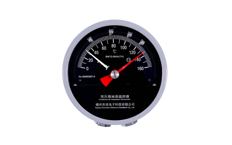
- Traditional WTI instruments indicate winding temperature by adding a load-related heating effect to oil temperature. That is a simulation, not a probe inside the winding.
- PT100 sensors measure directly at the point where they are installed, where electrical insulation and mechanical design allow it.
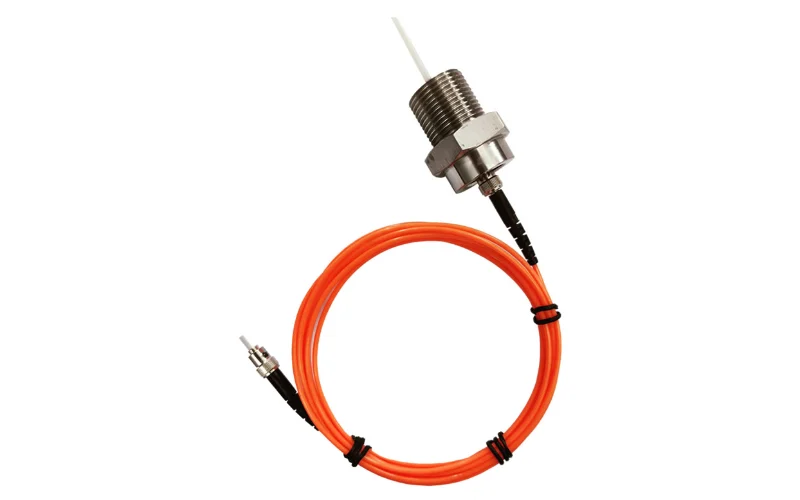
- Fiber optic probes can be placed close to predicted hot spots inside high-voltage windings, with an optical, electrically insulating sensing point.
Table of Contents
- 1. What Is Transformer Winding Temperature?
- 2. Winding Temperature vs Top-Oil vs Hot-Spot Temperature
- 3. How Is Transformer Winding Temperature Measured?
- 4. WTI, PT100 and Fiber Optic Measurement
- 5. Direct vs Calculated Winding Hot-Spot Temperature
- 6. What Causes Winding Temperature to Rise?
- 7. Online Winding Temperature Monitoring
- 8. Winding Temperature Monitoring Products
- 9. Transformer Winding Temperature FAQ
1. What Is Transformer Winding Temperature?
Transformer winding temperature reflects thermal conditions in the current-carrying winding conductors and the insulation around them. Load current flowing through the copper produces most of the heat. Stray and eddy losses add local heating, and the oil or air cooling system carries it away. Ambient temperature sets the baseline, and the winding geometry decides how the heat is distributed.
There is no single uniform temperature throughout a transformer winding. Axial and radial positions differ, cooling ducts change local flow, and the three phases rarely match exactly. Three terms therefore need to stay separate: average winding temperature, indicated winding temperature, and winding hot-spot temperature.
2. Winding Temperature vs Top-Oil vs Hot-Spot Temperature
| Parameter | What It Represents | Typical Measurement / Estimation | Why It Matters |
|---|---|---|---|
| Top-Oil Temperature | Oil near the upper part of the tank | Oil temperature indicator or sensor | Shows the bulk thermal state of the oil system |
| Winding Temperature | Average or indicated thermal condition of the winding | Resistance method, WTI indication, thermal calculation | Drives cooling control, alarm and trip logic |
| Winding Hot-Spot Temperature | Highest local temperature in the winding and its insulation | Thermal model, or an embedded sensor at a chosen location | Most closely tied to local insulation stress |
| Ambient Temperature | Air around the installation | Ambient sensor | Baseline for every thermal calculation |
Top-oil temperature is not winding temperature, and winding temperature is not the hottest internal hot spot. Under a sudden load increase the winding heats within minutes while the oil lags behind, so the gap between the two readings widens. The same logic is explained in more depth for transformer winding hot-spot temperature, including why the hot spot position changes from one design to the next.
3. How Is Transformer Winding Temperature Measured?
Four approaches are in common use: a winding temperature indicator, PT100 or RTD sensors, fiber optic probes, and a calculated thermal model. They answer different questions. A WTI gives a practical indication for control and protection. An RTD or fiber probe reports the temperature at its own physical location. A thermal model estimates what no sensor sees.
No method is best everywhere. The choice depends on transformer type, voltage level, whether the winding is still accessible, and where the measurement has to be taken. Selecting a transformer winding temperature sensor only makes sense after those points are settled.
4. WTI, PT100 and Fiber Optic Measurement
| Method | What It Measures | Direct or Indirect | Electrical Isolation | Typical Transformer Application |
|---|---|---|---|---|
| Traditional WTI | Top-oil temperature plus load-related heating | Indirect (simulated) | Bulb sits in the oil pocket, away from the winding | Oil-immersed transformers: indication, cooling control, alarm, trip |
| PT100 / RTD | Temperature at the installed point | Direct, at that point | Depends on insulation design and installation | Dry-type windings, oil and accessible structural points |
| Fiber Optic Sensor | Temperature at the probe tip | Direct, at that point | Optical, electrically insulating sensing point | Embedded hot-spot points in high-voltage windings |
| Thermal Model | Estimated hot-spot temperature | Calculated | No sensor at the winding | In-service units without embedded sensors |
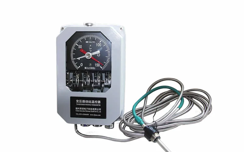
WTI instruments work by thermal image. A current transformer feeds a small heater next to the sensing element, and the dial shows top-oil temperature plus the simulated winding gradient. A winding temperature indicator is reliable for fan control and over-temperature contacts, but it does not place a probe at the conductor. Its accuracy depends on calibration against the factory heat-run gradient.
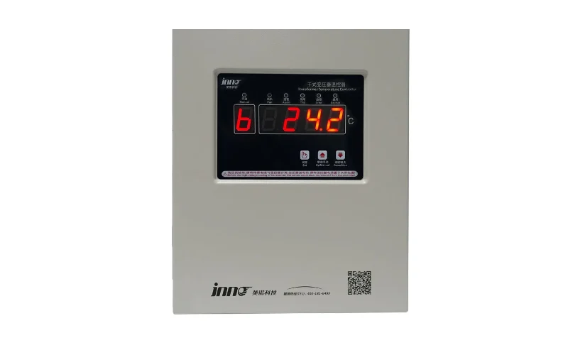
PT100 sensors are mature, inexpensive and compatible with most controllers. In dry-type transformers they sit at designed positions in or beside the windings and feed display, alarm and fan-control functions. Inside high-voltage oil-immersed windings, suitability comes down to insulation and wiring design, which is where the PT100 versus fiber question gets decided.
Fiber optic probes carry the signal as light, so there is no metal at the sensing point. The advantages are electrical isolation, immunity to electromagnetic interference, a small probe, and direct measurement at a hot-spot position chosen in the design. These strengths are about the environment inside an energized winding, not about beating every RTD on accuracy. INNOFZ explains the sensing principle on its fiber optic temperature monitoring page.
5. Direct vs Calculated Winding Hot-Spot Temperature
A calculated hot spot starts from top-oil temperature, load current, the winding-to-oil gradient and the transformer's thermal parameters. It works on units with no embedded sensors, and it gives a continuous estimate. Its quality depends on model inputs and on whether cooling and loading match the assumptions.
Direct measurement puts a sensor at a selected winding location, so the reading is the actual temperature at the installed sensing point. It also only tells you about that point. A probe 50 mm from the true hottest conductor will read differently, which is why placement follows the thermal design.
Calculated and direct values answer different questions. The model covers the whole unit; the probe verifies what happens at chosen locations. Comparing the two over several load cycles often tells you more than either number alone. More on this combination is covered under transformer winding hot-spot monitoring.
In practice, a unit already in service usually relies on WTI and a thermal model, because opening a winding is rarely realistic. New high-voltage or critical transformers can plan embedded fiber probes with the winding drawings. Dry-type designs typically use PT100 at designed positions, with fiber added where isolation or direct hot-spot data is needed. Not every transformer needs embedded winding sensors.
6. What Causes Winding Temperature to Rise?
| Condition | Temperature Effect | Monitoring Clue |
|---|---|---|
| High load current or overloading | Copper losses rise with current squared | Winding temperature climbs with load |
| Harmonic current | Extra eddy and stray losses | Higher temperature than load alone predicts |
| Fan or pump failure | Heat removal drops | No temperature drop when cooling should start |
| Blocked airflow or radiators | Slower heat rejection | Slow recovery after load reduction |
| High ambient temperature | Raises the thermal baseline | Uniform upward shift across channels |
| Oil circulation problems | Local flow restriction | One phase or section runs hotter |
| Contact resistance, unbalanced loading, localized losses | Concentrated local heating | Persistent phase-to-phase difference |
7. Online Winding Temperature Monitoring
A single temperature value says little without context. Online monitoring is more useful for the trend, the rate of rise, the relationship to load, differences between phases, the cooling state, and the alarm history. Temperature plus load plus cooling status describes the real thermal condition far better than a fixed threshold does.
A winding that heats faster than usual at the same load, or fails to cool after the fans start, points to a cooling or flow problem before an alarm point is reached. Alarm and trip settings still follow the manufacturer's data and the site protection philosophy. For the system view across oil, winding and hot spot, see transformer temperature monitoring.
8. Winding Temperature Monitoring Products
The values below come from the current INNOFZ product pages. Fiber optic probes and WTI instruments are listed separately because they measure different things.
| Product | Measurement Method | Sensor Type | Temperature Range | Accuracy | Typical Transformer Application |
|---|---|---|---|---|---|
| Polyimide Fiber Optic Temperature Sensor | Fluorescence afterglow lifetime | Point-type, 2–3 mm probe, fiber 0–80 m | -40 °C to +260 °C | ±0.5 °C to ±1 °C | Oil-immersed winding hot spot, spacer area, flexible routing |
| Armored Fiber Optic Temperature Sensor | Fluorescence afterglow lifetime | Point-type, armored, 2–3 mm probe, fiber 0–80 m | -40 °C to +260 °C | ±0.5 °C to ±1 °C | Oil-immersed winding, lead area, demanding internal routing |
Both probes use the same optical principle. The difference is mechanical: the fiber optic sensor for transformer windings with polyimide protection is thinner and more flexible for winding installation, while the armored version suits longer or harder internal routes.
| Product | Measurement Method | Channels / Contacts | Temperature Range | Accuracy | Communication / Output | Typical Transformer Application |
|---|---|---|---|---|---|---|
| BWR2 Winding Temperature Indicator | Thermal simulation from top-oil temperature and load current | 4 adjustable switch contacts | 0 °C to 160 °C | Class 1.5, max error ±2.4 °C | Pt100 or 4–20 mA by model; optional digital display with RS485 | Oil-immersed transformer indication, cooling control, alarm, trip |
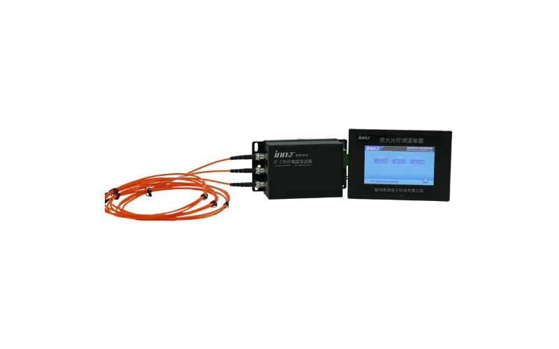
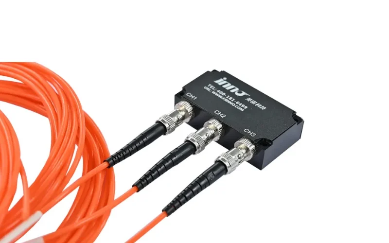
| 3-Channel Fiber Optic Temperature Transmitter | Fluorescent point-type optical sensing | 3 | -40 °C to 260 °C | ±0.5 °C to ±1 °C | RS485; display module and monitoring software | Three-phase winding hot-spot monitoring |
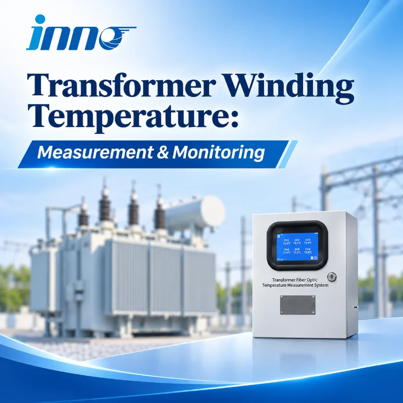
| Multi-Channel Fiber Optic Temperature Measurement System | Point-type optical measurement | 1 to 64, configurable | -40 °C to +240 °C | ±1 °C standard | RS485, Modbus, optional 4–20 mA, alarm output | Dry-type coils, oil-immersed windings, multi-point monitoring |
The BWR2 transformer winding temperature indicator belongs to the WTI category: it indicates simulated winding temperature and operates contacts. For three-phase hot-spot data, the 3-channel fiber optic temperature transmitter fits one probe per phase, and the multi-channel system covers larger point counts. A transmitter, indicator or system should be matched to the measuring point rather than treated as interchangeable.
9. Transformer Winding Temperature FAQ
What is transformer winding temperature?
It is the thermal condition of the winding conductors and nearby insulation under load. The value differs by position, so it is reported as average, indicated or hot-spot temperature.
What is the difference between winding temperature and hot-spot temperature?
Winding temperature is an average or indicated value for the winding. Hot-spot temperature is the highest local temperature inside it, and it can be higher than the indicated value.
How is transformer winding temperature measured?
Through a WTI indication, PT100 or RTD sensors at accessible points, embedded fiber optic probes, or a thermal model. The right choice depends on transformer type, voltage and installation stage.
Can fiber optic sensors directly measure transformer winding hot spots?
Yes, at the location where the probe tip is installed. Placement should follow the thermal design, since a probe only reports its own position.