
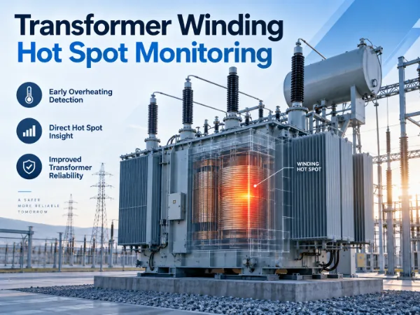
Transformer Winding Hot Spot Monitoring
Directly monitor critical winding temperatures inside transformers to improve thermal visibility, loading assessment, cooling evaluation and insulation life management.
Fiber optic temperature sensing enables direct measurement at selected internal winding locations where conventional external or estimated temperature values may not fully represent the actual hot spot.
Why Transformer Winding Hot Spots Matter
Transformer windings do not heat uniformly. Load current, cooling flow and local losses combine differently across winding sections, so the temperature at one location can differ meaningfully from another — and can also differ between phases.
- ●Load current affects winding temperature rise
- ●Cooling flow affects local temperature distribution
- ●Local losses may create hotter regions within a winding
- ●Temperature can differ between phases and winding sections
- ●Persistent overheating accelerates insulation aging
The hottest location inside a winding may operate under very different thermal conditions from top-oil temperature, ambient temperature or external measurements — see transformer temperature monitoring for the full picture across an asset.
Hot Spot Temperature vs Conventional Transformer Temperature Measurements
These measurements are complementary rather than interchangeable — each plays a different role in understanding transformer thermal condition.
| Measurement | What It Represents | Typical Role |
|---|---|---|
| Ambient Temperature | Surrounding air temperature at the installation site | Reference baseline for thermal calculations |
| Top Oil Temperature | Bulk oil temperature near the top of the tank | General thermal condition of the oil system |
| Winding Temperature Indicator / Estimated Winding Temperature | Calculated winding temperature based on top oil plus a modelled gradient | Cooling control, alarm and trip functions — see BWR2 Transformer Winding Temperature Indicator |
| PT100 Measurement | Contact resistance temperature measurement at an accessible point | Localized temperature monitoring at a fixed point |
| Direct Fiber Optic Hot Spot Measurement | Actual temperature at a selected internal winding location | Direct evidence of real winding thermal behavior |
Each row above answers a different question — direct hot spot measurement does not replace the others, it fills the gap they cannot cover.
Where Can Winding Hot Spots Develop?
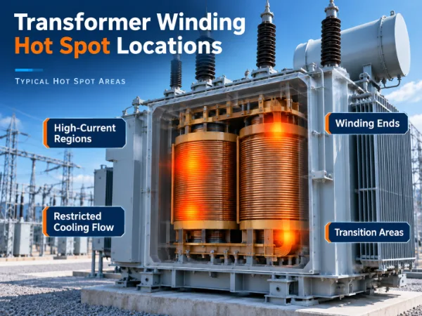
Hot spot locations depend on winding construction, current distribution, cooling arrangement, leakage flux and the overall transformer design — not on a single generic rule.
- ●High-current winding regions
- ●Areas with restricted cooling flow
- ●Winding ends and structural transition areas
- ●Selected phase-specific hot spot locations
- ●Regions identified during transformer thermal design
Sensor placement should follow transformer design information rather than a generic fixed location.
Direct Fiber Optic Winding Hot Spot Measurement
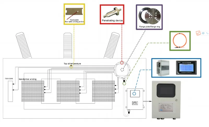
Fiber optic temperature sensors provide direct measurement at selected winding locations, with an electrically passive sensing point that is well suited to the electromagnetic and high-voltage environment inside a transformer.
- ●Direct measurement at selected winding locations
- ●Electrically passive sensing point
- ●Strong immunity to electromagnetic interference
- ●Suitable for high-voltage environments
- ●Multi-point winding temperature monitoring
- ●Long-term temperature trend monitoring
- ●Suitable for embedded sensing during transformer manufacturing
Direct Measurement vs Calculated Hot Spot Temperature
Calculated / Estimated Hot Spot
- ●Based on load current
- ●Oil or reference temperature
- ●Thermal model
- ●Transformer design assumptions
Useful for transformer thermal estimation, but results depend on model inputs and operating assumptions.
Direct Hot Spot Measurement
- ●Embedded sensing
- ●Actual selected winding locations
- ●Real load response
- ●Cooling response
- ●Phase comparison
- ●Actual thermal trend
Direct measurement and thermal calculation can complement each other rather than replace one another.
Why Multi-Point Winding Monitoring Matters
The purpose of multi-point monitoring is not simply to collect more temperature values, but to understand how heat is distributed across critical winding locations.
- ●Compare winding sections
- ●Compare phases
- ●Identify persistent temperature differences
- ●Observe load response across points
- ●Evaluate cooling effectiveness
- ●Track local thermal trends over time
Track Hot Spot Temperature Under Real Operating Load
Direct measurement lets you follow the relationship between load, cooling and winding temperature as it actually happens.
- ●Load increase vs temperature rise may indicate how sensitive a location is to loading
- ●Cooling activation vs temperature response can help identify cooling effectiveness
- ●Phase-to-phase comparison supports assessment of loading balance
- ●A persistent hot point across load cycles may justify further investigation
- ●Temperature recovery after load reduction is part of a normal thermal pattern
- ●Repeated abnormal thermal patterns can help identify locations that need attention
Winding Hot Spot Monitoring Across Transformer Types
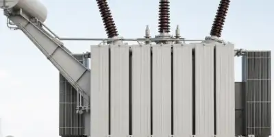
Oil-Immersed Power Transformers
Direct winding temperature monitoring inside oil-filled transformers.
Oil-Immersed Transformer Monitoring →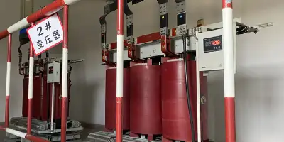
Dry-Type Transformers
Direct winding hot spot measurement can complement conventional PT100 temperature monitoring.
Dry-Type Transformer Temperature Monitoring →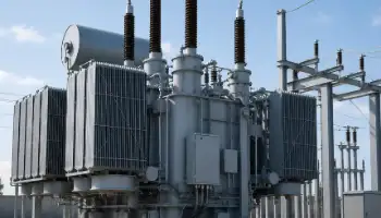
Power Transformers
Hot spot temperature as part of broader power transformer condition monitoring.
Power Transformer Monitoring →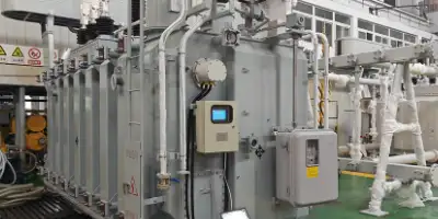
Substation Transformers
Continuous winding temperature monitoring for critical transformer assets in substations.
Substation Transformer Monitoring →Planning Hot Spot Monitoring for New and Existing Transformers
New Transformer Projects
- ●Review winding layout
- ●Identify critical thermal locations
- ●Determine sensing points
- ●Plan fiber routing
- ●Define monitoring channels
- ●Plan system integration
New transformer manufacturing provides the best opportunity to place sensors directly at selected internal winding locations.
Existing Transformer Retrofit
- ●Existing embedded sensor integration
- ●Monitoring unit upgrade
- ●Additional accessible temperature points
- ●Existing fiber optic sensing integration
- ●Remote monitoring integration
Adding sensors directly inside an existing winding depends on transformer construction and physical accessibility — not every existing transformer can accommodate this in the same way.
How Should Winding Hot Spot Sensors Be Positioned?
There is no universal fixed sensor position for every transformer winding.
Placement Depends On
- ●Transformer type
- ●Rated power
- ●Voltage level
- ●Winding structure
- ●Cooling arrangement
Also Depends On
- ●Expected thermal stress
- ●Transformer design data
- ●Number of phases
- ●Required sensing points
Sensor placement should be determined together with transformer design and manufacturing information.
From Embedded Sensors to Monitoring Data
See related solutions: Fiber Optic Temperature Monitoring, Transformer Temperature Monitoring and Transformer Monitoring.
Recommended Products for Winding Hot Spot Monitoring
Products directly relevant to winding hot spot sensing and multi-point winding temperature monitoring.
Fiber Optic Temperature Sensor for Winding Hot Spot Monitoring
Direct fiber optic sensing point for real-time transformer winding hot spot temperature monitoring.
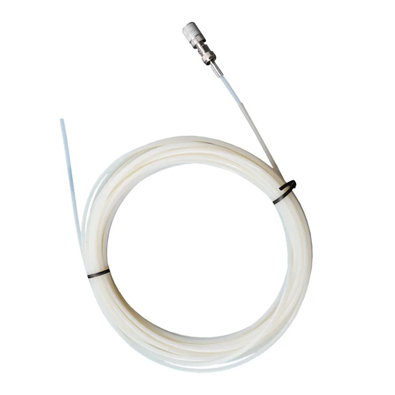
Polyimide Fiber Optic Temperature Sensor
Flexible polyimide-protected fiber optic probe for winding hot spot measurement, using fluorescent optical sensing.
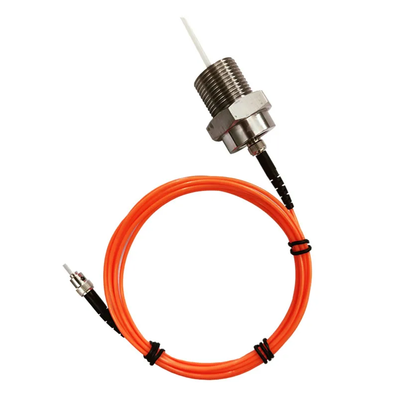
Armored Fiber Optic Temperature Sensor
Armored fiber optic sensor for oil-immersed transformer winding hot spot measurement, with reinforced protection and oil compatibility.
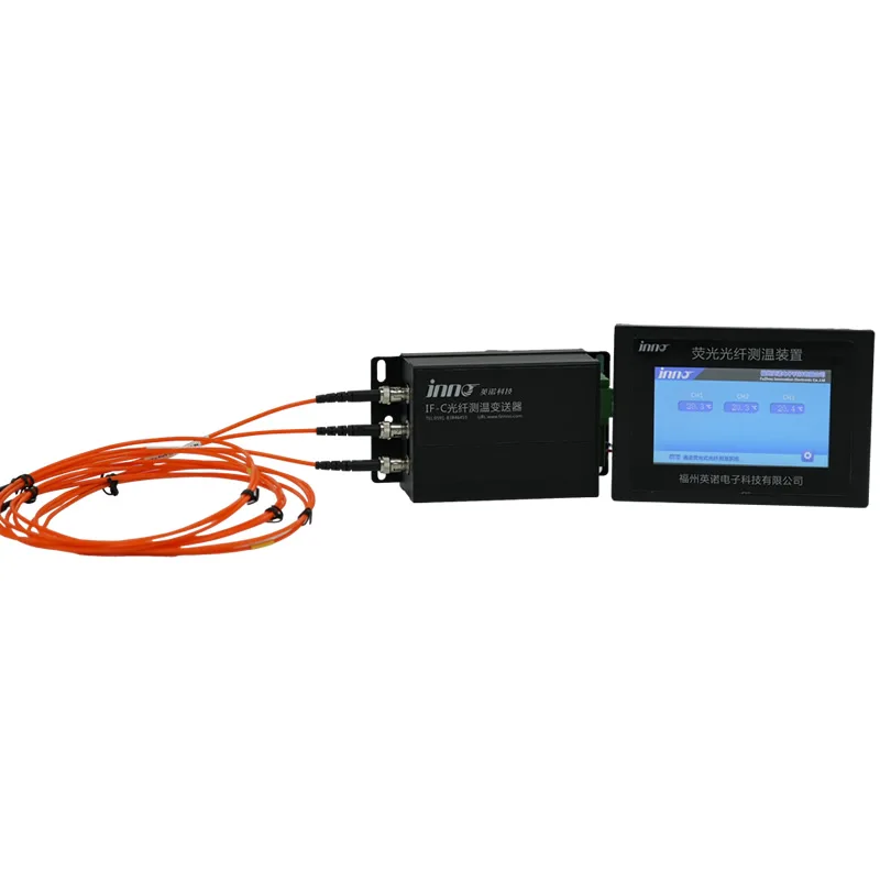
Multi-Channel Fiber Optic Monitoring System
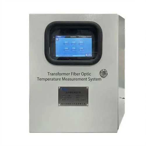
Multi-channel fiber optic temperature measurement and monitoring system for comparing winding sections and phases in real time.
Related Transformer Monitoring Solutions
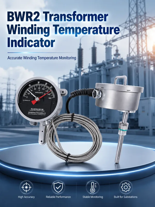
Transformer Temperature Monitoring
Full-picture temperature monitoring covering oil, winding and hot spot measurement together.
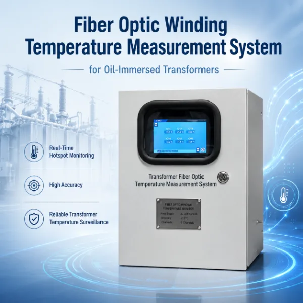
Fiber Optic Temperature Monitoring
The direct-sensing technology behind winding hot spot and dry-type transformer temperature monitoring.
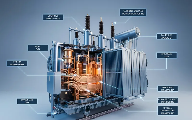
Transformer Monitoring
Broader condition monitoring combining temperature, DGA, partial discharge and more.
What Information Helps Us Recommend a Hot Spot Monitoring Configuration?
Transformer Information
- ●Transformer type
- ●Rated power
- ●Voltage level
- ●Number of phases
Winding Information
- ●Winding construction
- ●Winding drawings
- ●Cooling arrangement
- ●Expected hot spot locations
Monitoring Requirements
- ●Number of sensing points
- ●New transformer or retrofit
- ●Local display
- ●Alarm requirement
- ●Remote monitoring requirement
Winding drawings or thermal design information are particularly useful for evaluating sensor placement.
When Should Direct Hot Spot Monitoring Be Considered?
Frequently Asked Questions
What is transformer winding hot spot temperature?
It is the highest temperature occurring at a specific location inside a transformer winding, which can differ from the average or top-oil temperature.
Why is winding hot spot temperature different from top oil temperature?
Top oil temperature reflects the bulk oil condition, while local winding regions may run hotter due to load current, cooling flow and construction differences.
How is transformer winding hot spot temperature normally estimated?
It is commonly calculated from top oil temperature plus a modelled temperature gradient based on load and design assumptions.
Can winding hot spot temperature be measured directly?
Yes — fiber optic temperature sensors can be placed at selected internal winding locations to measure temperature directly.
Why are fiber optic sensors used inside transformer windings?
They are electrically passive and immune to electromagnetic interference, which suits the high-voltage environment inside a winding.
How many winding hot spot sensors are required?
This depends on transformer type, rated power, phases and the specific thermal locations that need to be monitored.
Where should fiber optic temperature sensors be installed in a transformer winding?
Placement should follow transformer design information and thermal analysis rather than a fixed generic position.
Can fiber optic hot spot sensors be installed in an existing transformer?
It depends on transformer construction and physical accessibility — new transformer manufacturing offers more placement flexibility than retrofit.
Can direct hot spot measurement be used together with WTI or transformer thermal models?
Yes — direct measurement and calculated or indicated temperature can be used together to give a more complete thermal picture.
Plan Winding Hot Spot Monitoring Before the Transformer Is Built
For new transformer projects, sensor locations and fiber routing can be planned together with the winding design. Send us your transformer type, winding information and monitoring requirements to evaluate suitable sensing points and monitoring architecture.







