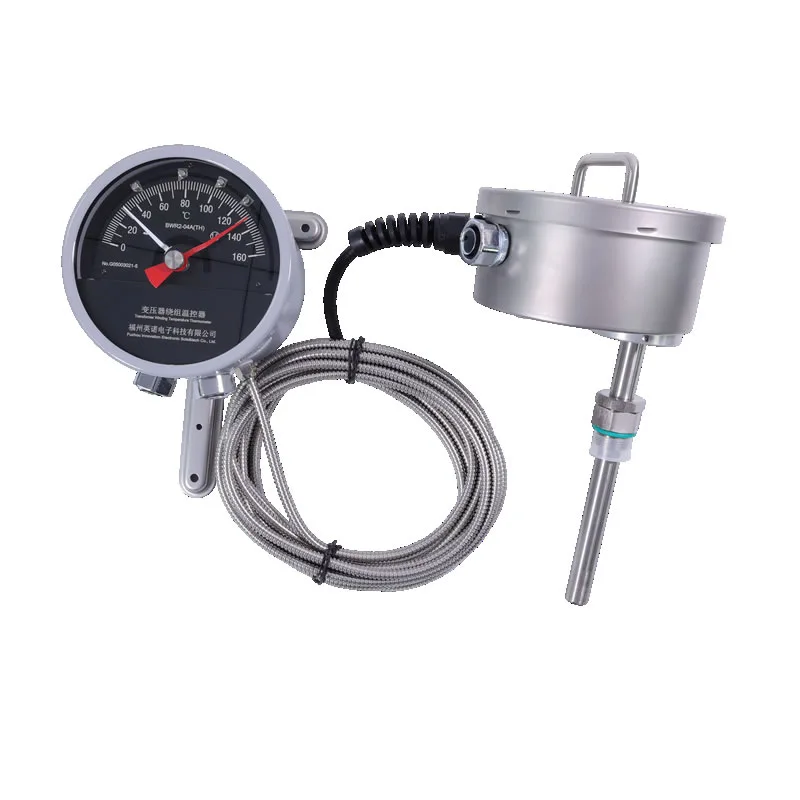

BWR2 WTI Gauge for Oil-Immersed Transformer Temperature Monitoring
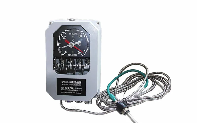
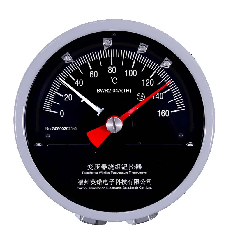
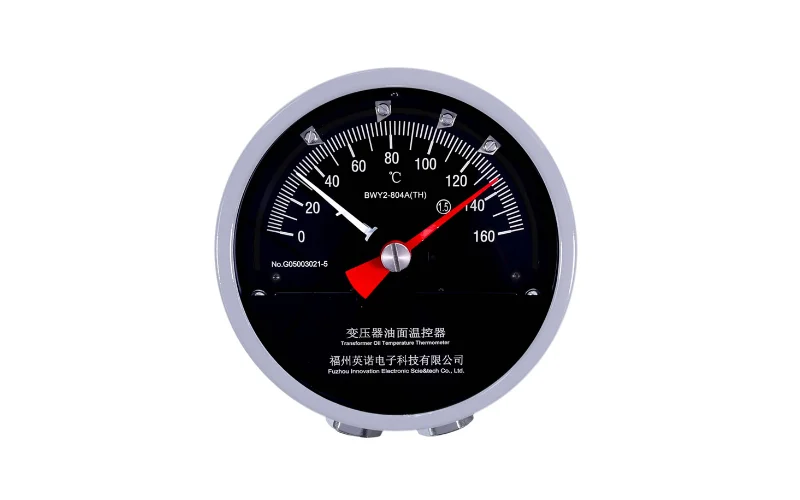
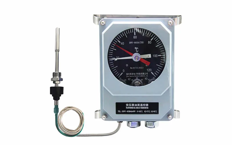
The BWR2 WTI gauge is used where oil-immersed transformers require local winding temperature indication, cooling control, signal alarm and trip protection. It helps operators monitor transformer thermal condition and supports safer operation under changing load conditions.
For transformer projects requiring remote display or signal transmission, the BWR2 winding temperature indicator can be configured with optional output and digital temperature display according to the selected model.
How the BWR2 Transformer Winding Temperature Indicator Works
The BWR2 transformer winding temperature indicator works by thermal simulation. The temperature bulb is installed in the compound transmitter, and the compound transmitter is inserted into the thermometer pocket on the top oil area of the transformer tank.
When the transformer operates without load, the indicated value reflects transformer oil temperature. When the transformer is loaded, the current signal from the transformer current transformer is adjusted by the compound transmitter and converted into additional heating on the sensing element. The final indicated value represents the combined effect of transformer top oil temperature and load-related winding temperature rise.
This working principle makes the product suitable for traditional transformer winding temperature indication, transformer cooling control, alarm contact output and over-temperature protection.
Key Functions of BWR2 Transformer Winding Temperature Controller
- Winding temperature indication for oil-immersed transformers
- Transformer top oil temperature and load-current thermal simulation
- Adjustable switch contacts for alarm, cooling control and trip protection
- Optional signal output for remote temperature indication
- Optional digital temperature display for remote display and signal control
- Suitable for transformer control cabinets and transformer temperature monitoring panels
- Designed for transformer cooling system control and over-temperature protection
BWR2 Winding Temperature Indicator Model Selection Guide
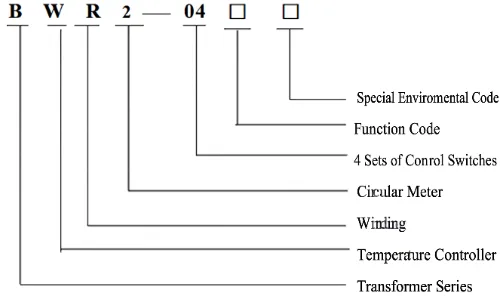
The BWR2 transformer winding temperature indicator can be selected according to switch quantity, output signal and special environmental application requirements. The model code helps define the configuration for transformer temperature indication, signal output and field environment.
| Model Code Item | Code | Meaning |
|---|---|---|
| Product Series | BWR2 | Transformer winding temperature controller / winding temperature indicator series |
| Control Switch Quantity | Configured by requirement | Switch contact quantity selected according to project requirement |
| Function Code | A | Pt100 output |
| Function Code | J | 4-20mA output, two-wire type |
| Special Environment Code | TH | Suitable for humid tropical areas |
| Special Environment Code | TA | Suitable for dry tropical areas |
| Special Environment Code | T | Suitable for dry and humid tropical areas |
BWR2 Transformer WTI Gauge Technical Specifications
| Product Name | Transformer Winding Temperature Indicator |
|---|---|
| Product Series | BWR2 Series |
| Application | Oil-immersed transformer winding temperature indication and control |
| Operating Ambient Temperature | -40°C to +65°C |
| Relative Humidity | ≤95% at 25°C |
| Measuring Range | 0°C to 160°C |
| Accuracy | Class 1.5; maximum allowable error at detection point ±2.4°C |
| Switch Contacts | 4 adjustable switch contacts |
| Switch Rated Power | AC220V / 5A |
| Capillary Length | According to the last group of digits in the instrument number |
| Protection Grade | IP55 |
BWR2 Compound Transmitter for Transformer Winding Temperature Control
The compound transmitter is an important part of the BWR2 transformer winding temperature indicator. It receives the current signal from the transformer current transformer and works with the temperature sensing element to simulate winding temperature rise under load.
This configuration allows the winding temperature indicator to provide local temperature indication and control signals for transformer cooling, alarm and protection circuits.
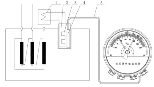
| No. | Component Name |
|---|---|
| 1 | Current Transformer |
| 2 | Transmitter |
| 3 | Heating Element |
| 4 | Temperature Sensing Element |
| 5 | Capillary Tube |
| Component | Compound Transmitter |
|---|---|
| Operating Ambient Temperature | -40°C to +65°C |
| Relative Humidity | ≤95% at 25°C |
| Input Signal | Transformer CT secondary current, 0.5A to 5.0A |
| Output Signal | Pt100 platinum resistance signal |
| Temperature Bulb Size | Φ18 × 150 mm |
| Mounting Thread | M27 × 2 mm |
| Protection Grade | IP55 |
BWR2 Winding Temperature Indicator Dimensions and Structure
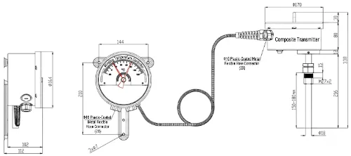
The BWR2 winding temperature indicator and compound transmitter are supplied with mechanical dimension drawings for transformer side-wall installation, thermometer pocket installation and capillary tube routing. Please confirm the final product drawing before transformer body design, panel design or site installation.
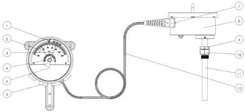
| No. | Component Name | No. | Component Name |
|---|---|---|---|
| 1 | Switch Contact Setting Pointer | 7 | Cable Entry Hole |
| 2 | Temperature Indicating Pointer | 8 | Compound Transmitter |
| 3 | Maximum Temperature Recording Pointer | 9 | Sealing Bolt |
| 4 | Maximum Recording Pointer Reset Knob | 10 | Mounting Screw |
| 5 | Zero Adjustment Knob | 11 | Temperature Bulb / Temperature Sensor |
| 6 | Cable Entry Hole for Φ16 Plastic-Coated Hose Connector | 12 | Capillary Tube Covered with Stainless-Steel Hose |
Adjustable Switch Contacts for Transformer Alarm and Cooling Control
The BWR2 winding temperature indicator includes adjustable switch contacts that can be used for transformer signal alarm, cooling control and over-temperature trip protection. The contact settings can be configured according to transformer operation and protection requirements.
| Switch Contact | Factory Standard Setting | Typical Use |
|---|---|---|
| K1 | 50°C | Configured according to project requirement |
| K2 | 75°C | Configured according to project requirement |
| K3 | 100°C | Configured according to project requirement |
| K4 | 120°C | Configured according to project requirement |
BWR2 WTI Gauge Wiring Diagram Overview
The BWR2 transformer winding temperature controller supports wiring for control switch output, CT current input and Pt100 signal output according to the selected model and actual product wiring diagram.
| Wiring Item | Function |
|---|---|
| K1 / K2 / K3 / K4 | Control switch output terminals |
| CT Input | Transformer current transformer secondary current input |
| Pt100 Output | Platinum resistance temperature signal output |
Optional Digital Temperature Display for BWR2 WTI Gauge
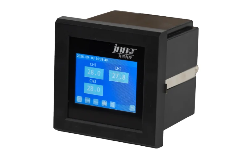
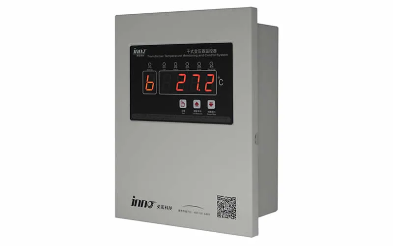
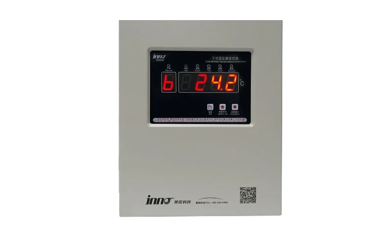
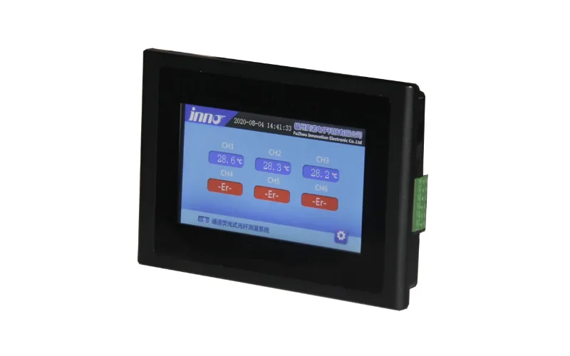
The optional digital temperature display can be used together with the BWR2 transformer winding temperature indicator for remote temperature indication, signal transmission and signal control. It is suitable for transformer control panels, remote monitoring cabinets and centralized temperature display applications.
| Accessory | Digital Temperature Display |
|---|---|
| Operating Ambient Temperature | -10°C to +50°C |
| Relative Humidity | ≤85% |
| Power Supply | AC/DC100–265V, 50–60Hz |
| Output Signal | 4-20mA analog current, RS485 communication |
| Display Type | Digital tube display |
| Accuracy | Class 1.0 |
Digital Temperature Display Model Selection for BWR2 WTI Gauge
The optional digital temperature display can be selected according to input signal, working power supply, relay quantity and optional output or communication function. It is used for remote temperature indication, signal transmission and control output in transformer monitoring panels.
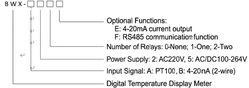
| Selection Item | Code | Meaning |
|---|---|---|
| Product Type | BWX | Digital temperature display |
| Input Signal | A | Pt100 input |
| Input Signal | B | 4-20mA input, two-wire type |
| Working Power Supply | 2 | AC220V |
| Working Power Supply | 5 | AC/DC100–264V |
| Relay Quantity | 0 / 1 / 2 | 0: none; 1: one relay; 2: two relays |
| Optional Function | E | 4-20mA output |
| Optional Function | F | RS485 communication function |
Digital Temperature Display Installation Dimensions
The optional digital temperature display is designed for embedded panel installation. It can be mounted into the reserved opening of the control panel for remote winding temperature indication and signal control.
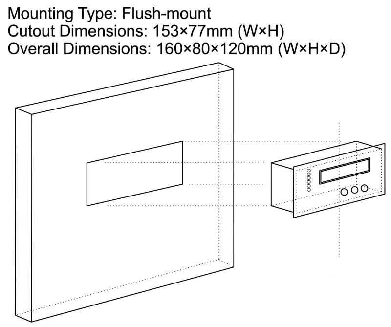
| Installation Method | Embedded installation |
|---|---|
| Panel Opening Size | 153 × 77 mm |
| Overall Dimensions | 160 × 80 × 120 mm |
Installation Overview for BWR2 Transformer Winding Temperature Indicator
The BWR2 transformer winding temperature indicator should be installed vertically on the transformer body. The temperature bulb should be inserted into the thermometer pocket filled with transformer oil, and the capillary tube should be properly fixed during installation.
...
| Installation Item | Requirement |
|---|---|
| Indicator Installation | Vertically fixed on the transformer side wall with 3 M6 bolts |
| Temperature Bulb Installation | Thermometer pocket should be filled with transformer oil before installation |
| Temperature Bulb Position | Temperature bulb should be inserted to the bottom of the thermometer pocket and fixed |
| Capillary Tube Fixing | Capillary tube should be properly fixed every 300mm |
| Extra Capillary Tube | Extra capillary tube should be coiled with a diameter greater than 200mm and fixed properly |
| Wiring Cable Section | Single wire cross-section recommended as 2.5mm² |
Applications of BWR2 Transformer Winding Temperature Indicator
The BWR2 transformer winding temperature indicator is suitable for oil-immersed transformer temperature indication, transformer cooling control and over-temperature protection applications. It can be used in transformer substations, industrial power distribution systems, power plants and transformer control cabinets.
- Oil-immersed power transformers
- Transformer cooling control systems
- Transformer temperature alarm and trip circuits
- Substation transformer monitoring panels
- Transformer control cabinets
- Remote temperature indication and signal transmission applications
WTI Gauge vs Fiber Optic Winding Temperature Monitoring
A traditional WTI gauge indicates simulated winding temperature based on transformer oil temperature and load-current thermal simulation. It is suitable for transformer winding temperature indication, cooling control and alarm protection.
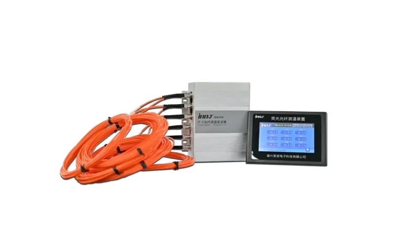
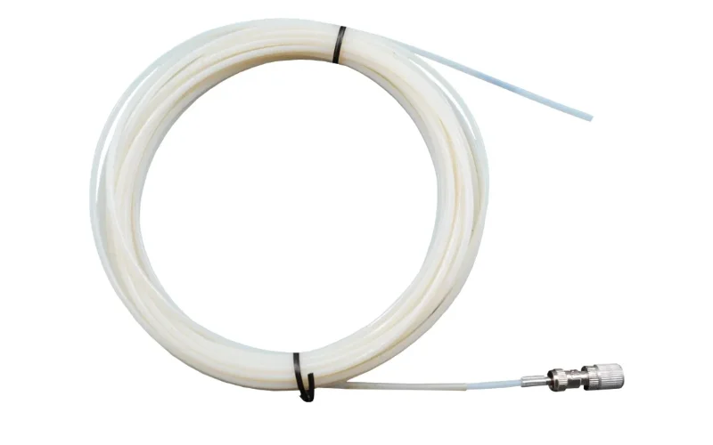
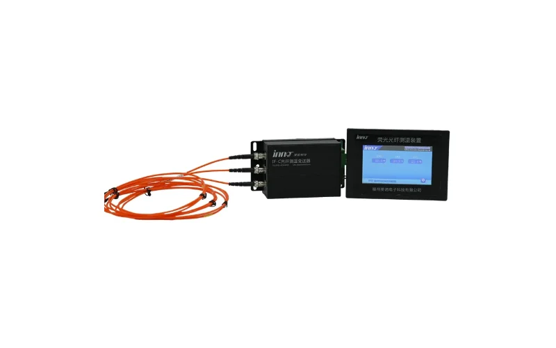
Fiber optic winding temperature monitoring is different. It uses fiber optic temperature sensors installed near the winding area for direct hot spot temperature measurement. For transformer projects that require direct winding hot spot measurement, fiber optic temperature monitoring can be considered together with traditional WTI temperature indication.
| Item | BWR2 WTI Gauge | Fiber Optic Winding Temperature Monitoring |
|---|---|---|
| Temperature Method | Thermal simulation | Direct optical temperature measurement |
| Typical Use | Local indication, alarm, cooling control and trip protection | Direct winding hot spot monitoring |
| Installation Position | Transformer thermometer pocket and side wall | Near winding hot spot measurement points |
Frequently Asked Questions About BWR2 Transformer Winding Temperature Indicator
What is a BWR2 transformer winding temperature indicator?
The BWR2 transformer winding temperature indicator is a WTI gauge used for oil-immersed transformer winding temperature indication, cooling control, alarm output and over-temperature protection.
What does WTI mean in transformer temperature monitoring?
WTI means winding temperature indicator. In transformer applications, it is commonly used to indicate simulated transformer winding temperature and provide control signals for transformer cooling and protection systems.
How does the BWR2 WTI gauge indicate winding temperature?
The BWR2 WTI gauge uses top oil temperature and load-current thermal simulation. The compound transmitter adds load-related temperature rise to the sensing element, allowing the indicator to show simulated transformer winding temperature.
Can the BWR2 winding temperature indicator support remote display?
Yes. The BWR2 transformer winding temperature indicator can be used with an optional digital temperature display for remote indication, signal transmission and control output according to the selected configuration.
What is the difference between a WTI gauge and fiber optic hot spot monitoring?
A WTI gauge uses thermal simulation, while fiber optic hot spot monitoring directly measures temperature at selected winding measurement points. The two methods can serve different transformer monitoring requirements.
Where is the temperature bulb installed?
The temperature bulb is installed in the compound transmitter, and the compound transmitter is inserted into the thermometer pocket on the top oil area of the transformer tank.
Request BWR2 Transformer Winding Temperature Indicator Configuration
For project selection, please provide the transformer type, required output signal, switch contact requirement, remote display requirement and installation environment. INNOFZ can help select a suitable BWR2 winding temperature indicator configuration for your transformer temperature monitoring application.