

What Is a Load Tap Changer in a Transformer
Date: 2026年11月2日 10:51:31
- Moving a transformer's connection from one winding tap to another changes its effective turns ratio, and with it the voltage ratio. A load tap changer does this while the transformer stays energized and carries load.
- OLTC is the common international abbreviation for on-load tap changer. In North American practice the same device is usually called an LTC.
- Each tap position is a fixed connection point on the regulating winding. Voltage is adjusted in discrete steps, not continuously.
- Load current cannot be interrupted during a tap change, and two adjacent taps cannot be bridged directly. Every OLTC therefore uses a transition stage that limits the circulating current.
- Off-circuit (de-energized) tap changers also alter the ratio, but only with the transformer out of service.
Table of Contents
- What Does a Load Tap Changer Do?
- Why Transformers Need Tap Changers
- How an On-Load Tap Changer Works
- Main Parts of a Load Tap Changer
- On-Load vs Off-Circuit Tap Changers
- Common OLTC Designs
- Load Tap Changer Problems and Condition Monitoring
- Load Tap Changer FAQ
1. What Does a Load Tap Changer Do?
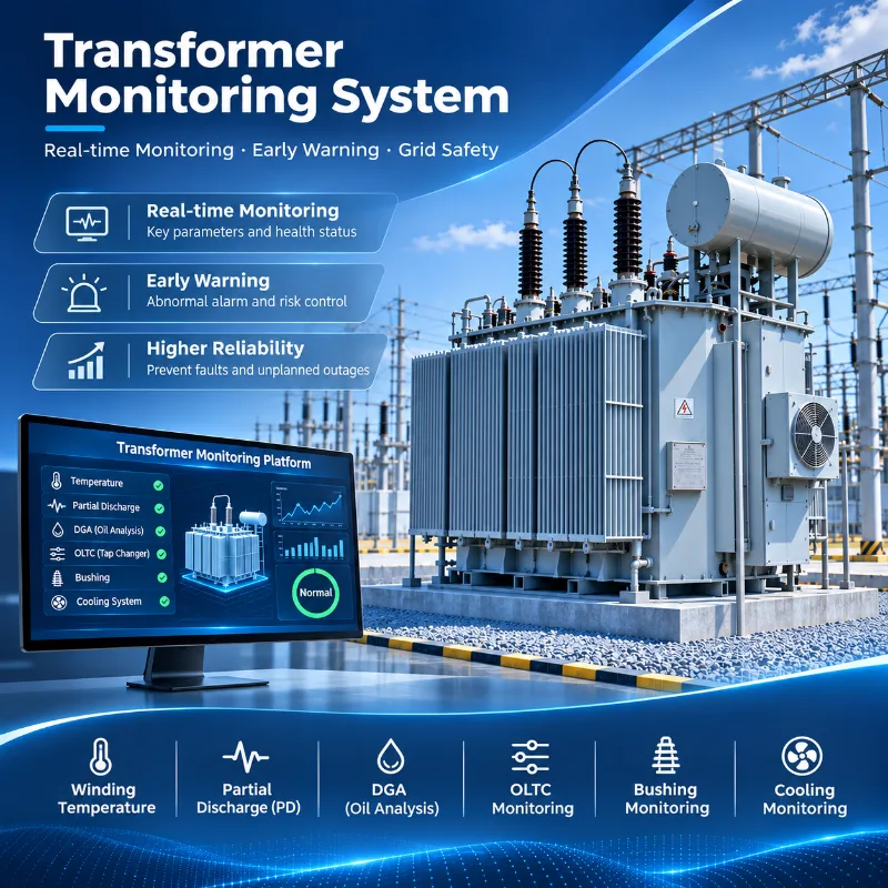
A load tap changer adjusts a transformer's voltage ratio by selecting a different tap on the regulating winding, which changes the number of turns in the circuit. It does not raise or lower voltage directly. It changes the effective turns ratio, and the output voltage follows. Because the change happens while the transformer is energized and loaded, voltage regulation continues without an outage.
The underlying relationship is simple. Voltage on each side of a transformer scales with the number of turns on that side, so altering the connected turns shifts the ratio. Operators describe the present setting as the transformer tap position, and a voltage-control scheme raises or lowers it step by step.
2. Why Transformers Need Tap Changers
Grid voltage never sits still. Loading changes through the day, upstream voltage drifts with network switching, and generation output moves with demand and weather. A transformer with one fixed turns ratio passes all of that straight through to the secondary side.
Where the secondary voltage has to stay inside a required range, the ratio needs some flexibility. Load tap changers matter most where that adjustment must happen without interrupting service, which is common on substation and generator step-up units; see power transformer monitoring for how these assets are typically treated.
Not every transformer carries an OLTC. Some use off-circuit tap changers instead, and the choice depends on transformer duty and how much voltage regulation the application demands.
| Operating Need | Tap Changer Role |
|---|---|
| Changing system voltage | Adjust transformer ratio |
| Load variation | Maintain the required voltage range |
| Continuous service requirement | Allow tap adjustment without de-energizing the transformer |
3. How an On-Load Tap Changer Works
The sequence runs like this: a voltage correction is needed, the control system commands a tap change, the next tap is prepared, load current is transferred through a transition impedance, and the old tap is released. The transformer then operates at its new tap position.
Why not simply disconnect one tap and connect the next? Because the transformer is carrying load. Breaking the connection would interrupt load current and cause arcing at the contacts. Closing onto the next tap with no impedance in between would short-circuit the winding section separating the two taps. A load tap changer has to avoid both.
3.1 Tap Selection
Tap selection happens before any current is transferred. In many designs a selector moves to the adjacent tap while carrying no switching duty, so the tap is ready when the transfer begins. Some arrangements combine selecting and switching in a single element, so this separation is not universal.
3.2 Current Transfer
Current transfer is the delicate part. In designs with a diverter switch, an energy-storage mechanism, commonly a spring, drives the switch quickly through the transition. For a brief interval both taps are bridged through a transition impedance. Resistors or reactors serve this purpose depending on design, and they hold the circulating current between the two taps to an acceptable level. Once the new tap carries the load, the previous one is released.
4. Main Parts of a Load Tap Changer
OLTC architecture varies by manufacturer and transformer type. Some units have a separate oil compartment for the switching element, others do not, so the list below describes common elements and not a universal bill of materials.
| Component | What It Does |
|---|---|
| Tap selector | Chooses the winding tap to be connected next |
| Diverter switch / switching element | Transfers load current from the old tap to the new one |
| Transition resistor or reactor | Limits circulating current while two taps are bridged |
| Motor drive unit | Supplies the mechanical energy for each tap change |
| Drive shaft and gearing | Carries motion from the drive to the tap changer |
| Tap position indicator | Shows, locally or remotely, the position currently in service |
| Oil compartment (where fitted) | Contains the switching element and its insulating oil |
5. On-Load vs Off-Circuit Tap Changers
Both change the turns ratio. What separates them is whether the transformer must be de-energized first. An off-circuit tap changer, also called a de-energized tap changer (DETC), is simpler but requires an outage before the tap position is changed. An OLTC offers in-service regulation at the cost of greater mechanical complexity.
| Feature | On-Load Tap Changer | Off-Circuit Tap Changer |
|---|---|---|
| Transformer energized during tap change | Yes | No, must be de-energized |
| Typical voltage regulation need | Frequent or continuous adjustment | Occasional or seasonal adjustment |
| Mechanical complexity | Higher | Lower |
| Frequency of operation | Can operate many times in service | Rarely operated |
| Typical application | Transmission, substation and generator transformers needing live regulation | Units where ratio is set once and seldom changed |
Neither is better in every case. The right choice follows from how the transformer is used.
6. Common OLTC Designs
OLTCs can be classified in different ways depending on the transition circuit, the switching technology and the physical arrangement. These categories overlap, so one unit can belong to several at once.
- By transition impedance: resistor-type designs use high-speed switching through transition resistors, while reactor-type designs use a reactor to bridge adjacent taps.
- By switching technology: oil-switching designs break current in oil, whereas vacuum designs use vacuum interrupters.
- By arrangement: some OLTCs sit in their own compartment, others are mounted inside the main tank.
Vacuum interrupters confine the switching arc inside sealed bottles, which reduces arcing-related oil contamination compared with traditional oil-switching diverter designs. Vacuum designs still have contacts, drives and mechanisms that wear and need inspection.
7. Load Tap Changer Problems and Condition Monitoring
An OLTC is a mechanism that moves and switches load current, so it ages in ways static parts do not. Typical problems include contact wear, abnormal contact resistance or overheating, motor drive abnormality, mechanical resistance or jamming, vibration changes, incomplete tap operation, tap position mismatch and, in designs that use oil for switching, oil deterioration.
No single reading separates these cases reliably. Continuous OLTC condition monitoring combines several signals, namely current, temperature, vibration, torque and tap position, and a deviation in one is read against the others. The OLTC condition monitoring parameters are covered in more depth in a dedicated article, and for fleet-level programs an online OLTC condition monitoring approach can feed maintenance planning.
For projects that require continuous operating data, the INNO-OLTC Transformer OLTC Online Monitoring System records these switching-related signals and provides event, trend and alarm information for condition assessment. Readings indicate abnormal behavior; final diagnosis still rests on inspection and maintenance judgment.
An OLTC is only one condition domain within a power transformer. Temperature, dissolved gas, partial discharge and bushing condition each carry different information, which is why transformer condition monitoring usually looks across all of them.
8. Load Tap Changer FAQ
8.1 What is a load tap changer in a transformer?
A load tap changer is a device that changes which winding tap a transformer uses, altering the turns ratio and therefore the voltage ratio. It operates while the transformer is energized and carrying load, allowing voltage regulation without an outage.
8.2 What is the difference between OLTC and LTC?
There is no functional difference. OLTC, short for on-load tap changer, is the common international term, while LTC, short for load tap changer, is widely used in North American practice. Both describe a tap changer that switches under load.
8.3 What is the difference between an on-load and off-circuit tap changer?
An on-load tap changer changes taps while the transformer is energized, using a transition stage to keep current flowing. An off-circuit tap changer is simpler but requires de-energizing the transformer before the tap position is changed.
8.4 Why do load tap changers need condition monitoring?
An OLTC contains moving parts and switches load current, so contacts, drive and mechanism wear gradually. Monitoring signals such as current, temperature, vibration, torque and tap position shows abnormal trends earlier than periodic inspection alone, though diagnosis still needs inspection.