
Generator Step-Up Transformer Monitoring for Power Generation
Direct fiber optic winding hot spot temperature measurement for generator step-up transformers, combined with DGA, partial discharge and critical component condition monitoring.
Monitor actual winding thermal behavior under generator load and cooling conditions, with embedded fiber optic sensors planned around critical transformer winding locations.
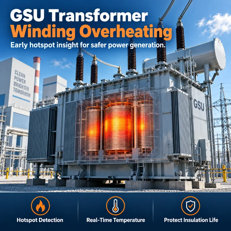
Why GSU Transformer Winding Hot Spots Matter in Power Generation
- ●Generator output directly affects transformer loading.
- ●High continuous loading can create winding thermal stress.
- ●Local winding hot spots may not be fully represented by top-oil temperature.
- ●Cooling condition changes affect winding thermal response.
- ●Repeated high-temperature operation contributes to insulation thermal aging.
- ●Direct temperature information at selected winding locations provides additional thermal visibility.
For critical generator step-up transformers, winding hot spot temperature is one of the most valuable thermal condition signals because it reflects what is happening at selected locations inside the winding under actual operating load.
Related: Transformer Winding Hot Spot Monitoring · Transformer Temperature Monitoring · Fiber Optic Temperature Monitoring
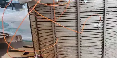
What Should Be Measured Inside a Generator Step-Up Transformer?
- ●Winding Hot Spot Temperature — direct measurement at selected thermally critical winding locations.
- ●Top-Oil Temperature — provides a reference for the overall transformer oil thermal condition.
- ●Transformer Load — allows winding temperature behavior to be evaluated together with generator output and transformer loading.
- ●Cooling Response — helps evaluate how winding and oil temperatures respond to cooling stages and changing operating conditions.
Additional condition signals such as DGA, partial discharge and bushing monitoring can be added according to transformer criticality and project requirements.
Direct Winding Hot Spot Measurement vs Estimated Temperature
| Temperature Method | What It Represents | Role in GSU Monitoring |
|---|---|---|
| Top-Oil Temperature | Overall transformer oil thermal condition | Thermal reference |
| Winding Temperature Indicator (WTI) | Indirect / simulated winding temperature indication | Conventional transformer temperature indication |
| Thermal Model | Calculated winding hot spot based on load, reference temperature and design assumptions | Engineering estimation |
| Fiber Optic Temperature Sensor | Direct temperature measurement at selected winding locations | Direct hot spot measurement |
Direct fiber optic temperature measurement complements conventional WTI and transformer thermal models rather than replacing them.
Related products: BWR2 Transformer Winding Temperature Indicator · Fiber Optic Temperature Sensor for Transformer Winding Hot Spot Monitoring
Fiber Optic Temperature Monitoring for Generator Step-Up Transformers
- ●Direct Winding Measurement — measure actual temperature at selected winding locations.
- ●Electrical Isolation — optical sensing is suitable for high-voltage insulation environments.
- ●EMI Immunity — fiber optic sensing avoids the electromagnetic interference limitations associated with conventional electrical signal transmission at the sensing point.
- ●Multi-Point Temperature Monitoring — compare temperature behavior across multiple winding locations and phases.
- ●Designed During Transformer Manufacturing — new GSU transformer manufacturing provides the best opportunity to plan sensor locations, fiber routing and monitoring channels.
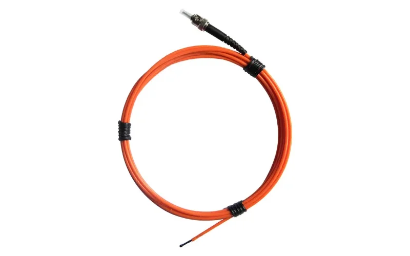
How to Plan Fiber Optic Hot Spot Monitoring for a New GSU Transformer
Review the Winding Thermal Design
Review winding structure, cooling path, current distribution and transformer thermal design information.
Identify Critical Hot Spot Locations
Determine selected sensing locations according to transformer design information rather than using one universal sensor position.
Plan Sensor Quantity and Fiber Routing
Define monitoring points, phase coverage, fiber routing and mechanical protection during transformer manufacturing.
Configure Monitoring Channels and Plant Integration
Match the number of sensing points with the monitoring unit and required local / remote data architecture.
Fiber optic sensor placement should be coordinated with the transformer designer or manufacturer before winding assembly whenever possible.
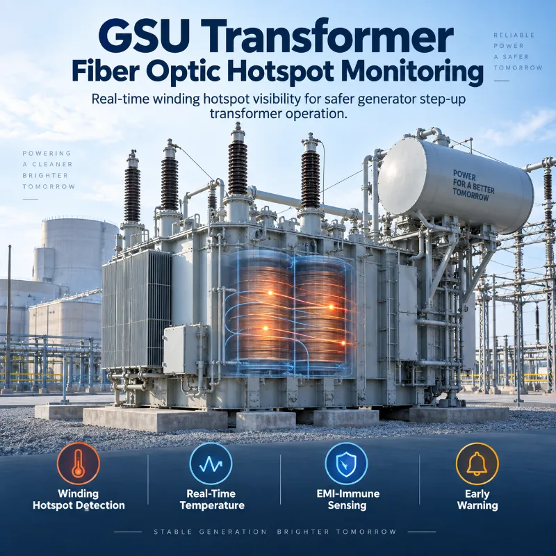
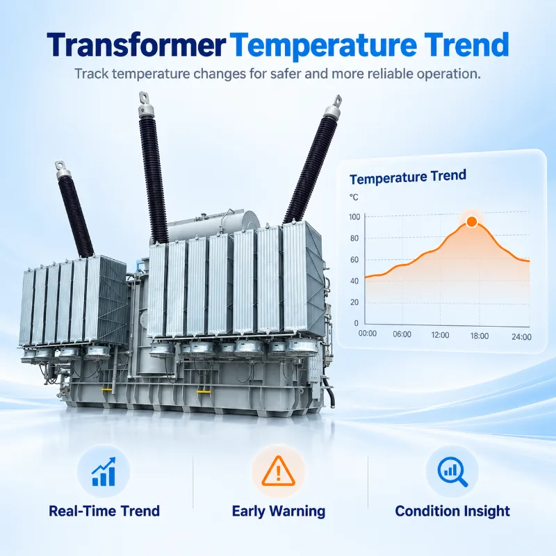
Track GSU Winding Temperature Under Generator Load
- ●Compare winding temperature with generator output.
- ●Observe temperature rise during increasing load.
- ●Compare temperature response after cooling stages change.
- ●Identify persistent phase or monitoring-point differences.
- ●Review repeated high-temperature operating periods.
Temperature trends become more valuable when they are evaluated together with actual transformer load and cooling behavior.
Why Multi-Point Winding Temperature Monitoring Matters
The purpose of multi-point monitoring is not simply to collect more temperature values, but to understand how heat is distributed across critical winding locations.
- ●Compare multiple winding locations.
- ●Compare phases.
- ●Observe local temperature differences.
- ●Identify persistent thermal imbalance.
- ●Evaluate load response.
- ●Evaluate cooling response.
Additional Condition Signals for Critical GSU Transformers
Dissolved Gas Analysis
Provides chemical evidence of developing internal thermal or electrical abnormalities.
Partial Discharge Monitoring
Provides evidence of developing discharge activity associated with transformer insulation.
Bushing Monitoring
Tracks condition changes in critical high-voltage transformer bushings.
OLTC Monitoring
Provides operating condition information for the on-load tap changer where applicable.
Also available: Transformer Oil Temperature, Level & Pressure Monitoring System.
From GSU Winding Sensors to Plant Condition Monitoring
The architecture should be configured around actual monitoring requirements and available system interfaces.
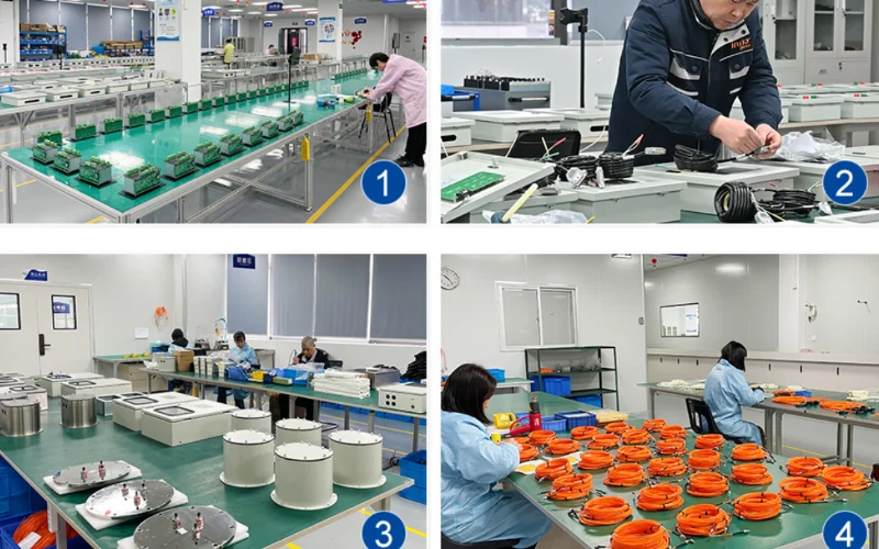
Why Choose INNO for GSU Fiber Optic Temperature Monitoring?
- ●Embedded Winding Temperature Sensing — fiber optic sensing options for direct measurement at selected winding locations.
- ●Multi-Point Monitoring Systems — sensors and multi-channel monitoring units for multiple winding temperature points.
- ●Support for Sensor Planning — sensor quantity, installation locations and fiber routing can be coordinated according to transformer design information.
- ●Complete Fiber Optic Temperature Monitoring Configuration — sensor probes, optical leads, monitoring units, displays and monitoring architecture can be configured according to project requirements.
DGA, partial discharge, bushing and OLTC monitoring can also be added when broader transformer condition monitoring is required.
New GSU Transformer or Existing Transformer Retrofit?
New GSU Transformer
- ●Best opportunity for embedded winding sensors
- ●Review thermal design
- ●Plan sensor locations
- ●Plan fiber routing
- ●Select monitoring channels
- ●Coordinate installation during transformer manufacturing
Existing Transformer
- ●Review existing embedded sensors
- ●Integrate existing fiber optic sensors where available
- ●Upgrade monitoring units
- ●Add accessible external temperature monitoring
- ●Add DGA / PD / bushing monitoring where required
Installing new fiber optic sensors directly inside an existing transformer winding depends on transformer construction, accessibility and the scope of transformer disassembly.
Recommended Products for GSU Temperature & Condition Monitoring
Fiber optic temperature monitoring options for GSU winding hot spots, plus complementary DGA, PD and bushing condition monitoring.
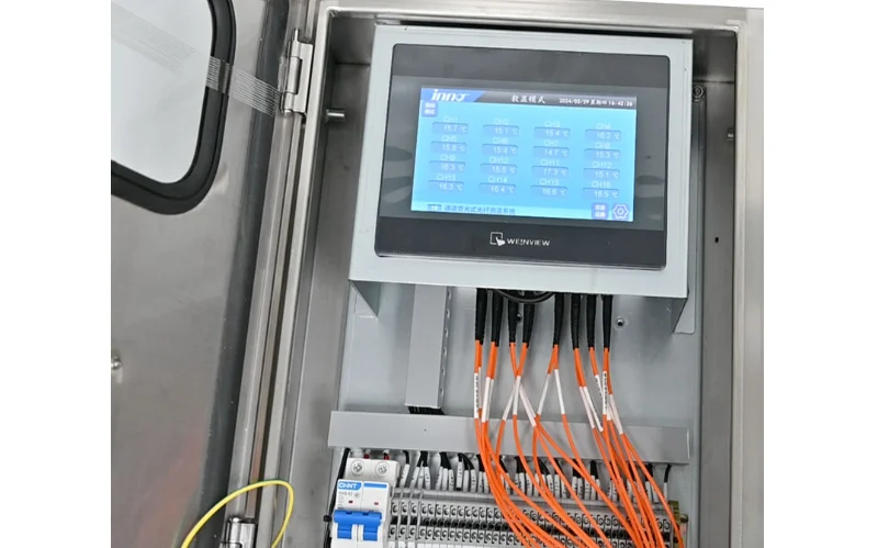
Fiber Optic Temperature Measurement System for Oil-Immersed Transformer
A complete fiber optic system for direct winding hot spot temperature measurement, suited to new GSU transformer projects.
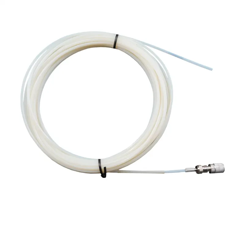
Fiber Optic Temperature Sensor for Transformer Winding Hot Spot Monitoring
The sensor element positioned at selected winding locations to provide direct hot spot temperature data.
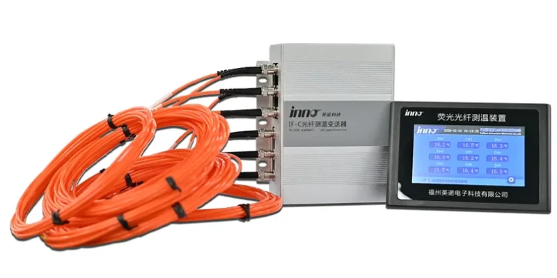
Multi-Channel Fiber Optic Temperature Measurement and Monitoring System
Monitors multiple winding locations and phases together, fitting GSU projects that need multi-point coverage.
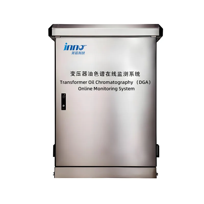
Online Dissolved Gas Analysis DGA Monitoring System for Transformer Oil
Adds chemical condition evidence alongside winding temperature data on critical GSU transformers.
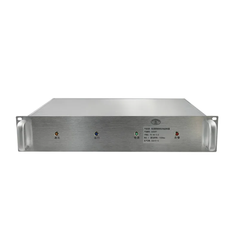
Transformer Partial Discharge Online Monitoring System
Continuous monitoring of discharge activity as a complementary insulation condition signal.
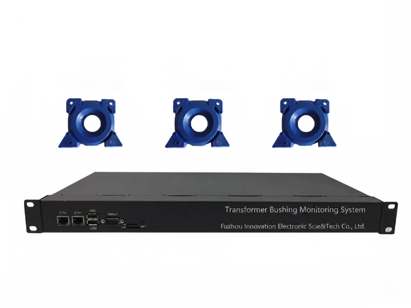
Transformer Bushing Monitoring System
Monitors condition changes in the GSU transformer's critical high-voltage bushings.
Related Monitoring Solutions
Related Transformer Applications
What Information Helps Us Plan GSU Fiber Optic Temperature Monitoring?
Transformer Information
- ●Transformer rating
- ●Voltage level
- ●Number of phases
- ●Transformer design / type
Winding Information
- ●Winding structure
- ●Winding drawings
- ●Thermal design information
- ●Cooling arrangement
- ●Expected hot spot locations
Monitoring Requirements
- ●Required sensing points
- ●Number of channels
- ●New transformer or retrofit
- ●Local display requirement
- ●Alarm / remote monitoring requirement
Winding drawings and thermal design information are especially useful for evaluating embedded fiber optic sensor locations.
Frequently Asked Questions
What is a generator step-up transformer?
A generator step-up (GSU) transformer connects a generator's output to the transmission system, stepping generator voltage up to transmission voltage.
Why is winding hot spot temperature important in a GSU transformer?
GSU transformers can experience significant and sustained loading tied to generator output, and winding hot spot temperature reflects thermal stress at selected locations inside the winding that top-oil temperature alone may not fully represent.
Can GSU winding hot spot temperature be measured directly?
Yes — fiber optic temperature sensors can be positioned at selected winding locations to provide direct measurement, most readily when planned during transformer manufacturing.
Why use fiber optic temperature sensors inside a GSU transformer?
Fiber optic sensing provides electrical isolation and avoids the EMI limitations of conventional electrical signal transmission at the sensing point, which suits the high-voltage winding environment.
How is direct fiber optic measurement different from WTI?
A winding temperature indicator (WTI) provides an indirect, simulated winding temperature reading, while a fiber optic sensor measures actual temperature at a specific winding location. The two are complementary rather than substitutes for one another.
How many fiber optic sensors should be installed in a GSU transformer?
The number of sensing points depends on winding design, phase configuration and project monitoring requirements, and is typically defined during sensor planning rather than fixed at one universal count.
Where should fiber optic temperature sensors be installed in the winding?
Sensor locations should be identified from the transformer's thermal design and winding drawings to target the locations most likely to reach higher temperature under load.
Can fiber optic sensors be installed in an existing GSU transformer?
Installing new sensors directly inside an existing winding depends on transformer construction, accessibility and the extent of disassembly involved; existing embedded fiber optic sensors, where already present, can often be integrated with a monitoring unit.
Plan GSU Winding Hot Spot Monitoring Before the Transformer Is Built
Send us your GSU transformer rating, winding drawings, thermal design information and required sensing points. We can help evaluate a fiber optic temperature monitoring configuration for selected winding hot spots.







