Fiber Optic Temperature Measurement in Transformers: Hot Spot Monitoring, Installation & Channel Selection
Date: 2026年9月27日 10:05:00
- What it is: Fiber optic temperature measurement places all-dielectric fluorescent probes directly inside transformer windings to read the true hot spot temperature, instead of estimating it from top-oil temperature and a thermal model.
- Why it matters: The winding hot spot sets the ageing rate of cellulose insulation. Every 6–7 °C rise above the design hot spot roughly doubles the insulation ageing rate.
- How it works: A light pulse excites a rare-earth phosphor at the probe tip. The phosphor's fluorescence decay time changes with temperature, and a demodulator converts it into a reading that is immune to EMI and high voltage.
- Installation: Probes are fitted in the factory during winding assembly, routed through the oil or air ducts, and brought out through a sealed tank-wall feedthrough plate to the monitoring unit.
- Channel selection: Small distribution transformers usually need 3–4 channels, medium power transformers 6–8, and large generator step-up or 500 kV units 8–16 or more, depending on phases, windings and cooling design.
- Output: The monitor gives local display, alarm and trip relays, cooling fan control and RS485/Modbus or IEC 61850 communication to SCADA.
Table of Contents
- 1. Why Transformer Hot Spot Temperature Matters
- 2. How Fiber Optic Temperature Measurement Works
- 3. Fiber Optic vs. Conventional Temperature Measurement
- 4. System Components and Technical Parameters
- 5. Installation of Fiber Optic Sensors in Transformers
- 6. Channel Selection Guide
- 7. Oil-Immersed vs. Dry-Type Transformer Applications
- 8. Alarm Settings, Cooling Control and System Integration
- 9. Typical Industries and Applications
- 10. FAQ
1. Why Transformer Hot Spot Temperature Matters
1.1 The Hot Spot Controls Insulation Life
The life of a transformer is the life of its paper insulation. Cellulose degrades through heat, moisture and oxygen, and heat is the dominant factor. The hottest point in the winding, usually near the top of the low-voltage or high-voltage winding where oil or air is warmest and leakage flux is strongest, ages fastest. That location decides when the insulation reaches end of life.
Loading guides such as IEC 60076-7 and IEEE C57.91 use the hot spot temperature to calculate relative ageing. For non-thermally-upgraded paper, the reference hot spot is 98 °C; above it, the ageing rate roughly doubles for every 6 °C increase. For thermally upgraded paper, the reference is 110 °C. For a full breakdown of design limits, see our guide to transformer temperature rise limits and ratings.
1.2 The Problem with Calculated Hot Spot Values
Traditional winding temperature indicators do not measure the winding. They measure top-oil temperature and add a heated element driven by a current transformer to simulate the winding-to-oil gradient. This "thermal image" method relies on factory heat-run data and assumes steady conditions. Under fast load changes, overloads, harmonic currents, cooling failures or ageing of the cooling system, the calculated value can differ from the real hot spot by 10 °C or more.
Direct measurement removes that uncertainty. It is why direct transformer winding hot spot monitoring is now specified for large power transformers, critical generation assets and transformers expected to run near or above nameplate rating. Uncontrolled hot spots are also one of the main root causes discussed in our article on transformer overheating causes, symptoms and prevention.
2. How Fiber Optic Temperature Measurement Works
2.1 Fluorescence Decay Principle
Most transformer winding sensors use the fluorescence lifetime method. The probe tip carries a small amount of rare-earth phosphor. The demodulator sends a short pulse of light down the fiber, the phosphor absorbs it and then glows. After the excitation stops, the glow fades exponentially. The decay time constant depends only on the temperature of the phosphor.
Because the reading is based on time, not light intensity, it is not affected by fiber bending, connector losses or light source ageing. The probe needs no recalibration over its service life and can be swapped between channels of the same demodulator.
2.2 Why Fiber Suits the Inside of a Transformer
- Fully dielectric: The probe and fiber contain no metal, so they do not distort the electric field or create a partial discharge path between windings.
- EMI immunity: Light signals are not affected by the strong magnetic and electric fields inside the tank.
- Oil compatibility: Jacket materials such as PTFE and polyimide are chemically stable in mineral oil, natural esters and synthetic esters at operating temperatures.
- Small size: Probes of 2–3 mm diameter fit into spacer slots and cooling ducts without changing the winding design.
The same principle applies in switchgear, busbars and other energized equipment, as explained in our overview of high voltage temperature measurement.
3. Fiber Optic vs. Conventional Temperature Measurement
The table below compares the common methods used to monitor transformer temperature.
| Method | What It Measures | Hot Spot Accuracy | Response to Load Change | Installed Inside Winding |
|---|---|---|---|---|
| Oil temperature indicator (OTI) | Top-oil temperature | Indirect only | Slow (oil time constant) | No |
| Winding temperature indicator (WTI, thermal image) | Top oil + simulated gradient | Estimated, ±5–15 °C | Moderate | No |
| PT100 / thermocouple | Local point temperature | Good, but only at low potential | Fast | Not in HV windings (metallic) |
| Fluorescent fiber optic probe | Actual winding hot spot | Direct, ±1 °C | Fast (<1 s) | Yes |
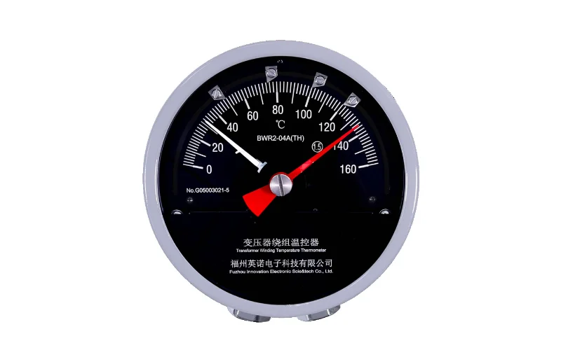
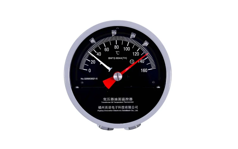
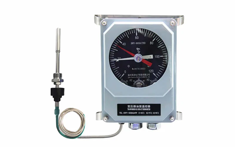
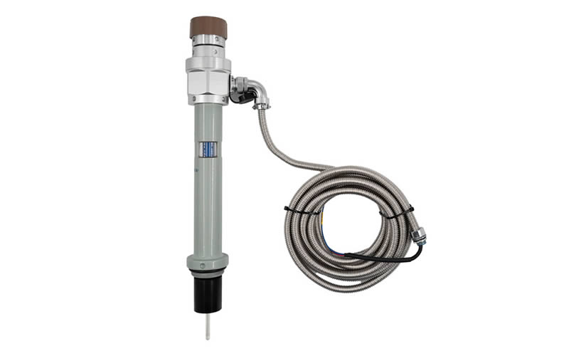
Mechanical indicators still have a role as backup protection. Products such as the BWY-802/803A oil temperature indicator and the BWR-04/06AJTH winding temperature indicator are often installed alongside a fiber optic system. For a detailed comparison, read oil temperature gauge vs. winding temperature gauge.
4. System Components and Technical Parameters
4.1 Main Components
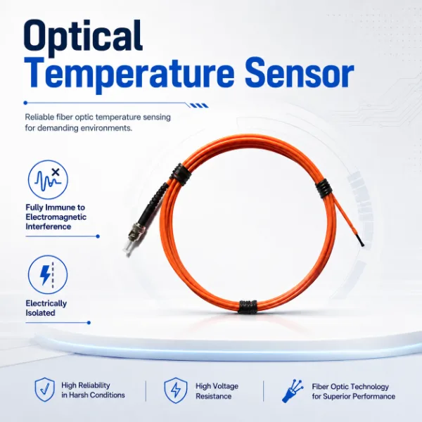
- Fiber optic temperature probes: Installed in the winding. Options include polyimide-jacketed sensors for windings, armored sensors for oil-immersed windings and general fluorescent fiber optic temperature probes.
- Tank-wall feedthrough: A sealed, oil-tight penetrator that carries the fibers through the tank wall without leaks.
- Extension cables: Fiber optic extension cables run from the tank wall to the monitoring cabinet.
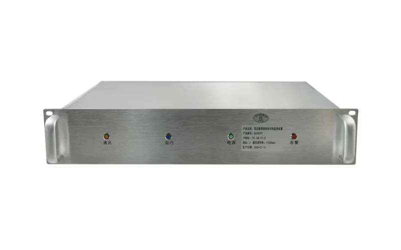
- Demodulator / transmitter: Converts the optical signal into temperature, for example a 3-channel fiber optic temperature transmitter or a 6-channel fluorescent demodulator.
- Display and control host: Shows readings, drives relays and communicates with SCADA, such as the integrated display host or LCD display instrument.
4.2 Typical Technical Parameters
| Parameter | Typical Value |
|---|---|
| Measuring principle | Fluorescence lifetime (decay time) |
| Measuring range | -40 °C to +200 °C |
| Accuracy | ±1 °C |
| Resolution | 0.1 °C |
| Response time | <1 s per channel |
| Probe diameter | 2–3 mm |
| Probe jacket | PTFE / polyimide / armored |
| Dielectric strength of probe | >100 kV |
| Channels per unit | 1, 3, 4, 6, 8, 12, 16, up to 64 |
| Fiber length (probe + extension) | Customizable, typically 1–20 m |
| Outputs | 4–20 mA, alarm/trip relays, fan control |
| Communication | RS485 Modbus RTU, Ethernet, IEC 61850 (optional) |
| Power supply | AC/DC 85–265 V or DC 24 V |
| Calibration | Not required over service life |
Values are typical; confirm final specifications against the datasheet of the selected model.
5. Installation of Fiber Optic Sensors in Transformers
5.1 When to Install
Winding probes are installed at the transformer factory during winding and active-part assembly. Retrofitting into an existing winding is generally not possible without untanking and rewinding, so the requirement should be written into the purchase specification. For existing transformers, top-oil and surface probes can be added during major maintenance, and the oil temperature, level and pressure monitoring system can be fitted without internal access.
5.2 Step-by-Step Installation Process
- Locate the hot spots: The transformer designer uses thermal calculations or CFD to find the expected hottest discs or turns, usually in the top 10–20% of each winding.
- Prepare spacers: A groove is cut in a radial or axial spacer so the probe tip sits in direct contact with the conductor insulation without mechanical stress.
- Place the probe: The probe tip is inserted and fixed with pressboard or tape. Contact with the conductor paper gives the best reading.
- Route the fiber: The fiber is led along the winding and clamping structure with gentle bends (usually no tighter than the minimum bend radius stated by the supplier), away from sharp edges and high field stress areas.
- Pass through the tank wall: All fibers exit through a dedicated feedthrough plate, usually on the tank cover or upper side wall, with oil-tight sealing.
- Test before drying: Check each channel for signal before vapour-phase drying, then again after drying and after tanking.
- Commission on site: Connect extension cables, set alarms, verify readings during the heat-run test and link the system to SCADA.
5.3 Installation Tips
- Install at least one spare probe per winding where possible; a failed internal probe cannot be replaced later.
- Label each fiber by phase and winding at both ends of the feedthrough.
- Protect the external fibers with conduit or armored cable between the tank and the control cabinet.
- Record hot spot readings during the factory heat run to validate the thermal model.
More detail on sensor placement is covered in transformer winding hot spot temperature measurement sensors.
6. Channel Selection Guide
6.1 Factors That Determine Channel Count
- Number of phases and windings: Each phase of each main winding (HV, LV, tertiary) can have its own hot spot.
- Transformer rating and criticality: Larger and more critical units justify more measuring points and redundancy.
- Cooling design: ONAN, ONAF, OFAF and ODAF cooling change where hot spots form.
- Reference points: Channels for top oil, bottom oil, core and ambient help build a complete thermal picture.
- Spare channels: Extra probes compensate for any probe damaged during manufacture.
6.2 Recommended Channel Configurations
| Transformer Type | Typical Rating | Recommended Channels | Typical Probe Locations |
|---|---|---|---|
| Dry-type distribution transformer | ≤ 2.5 MVA | 3–4 | One per phase LV winding + core/ambient |
| Oil-immersed distribution transformer | ≤ 20 MVA | 3–6 | One per phase LV or HV winding + top oil |
| Medium power transformer | 20–100 MVA | 6–8 | HV and LV per phase + top oil + spare |
| Large power / GSU transformer | > 100 MVA | 8–16 | HV, LV, tertiary per phase + oil + core + spares |
| Converter / HVDC / traction transformer | Project specific | 12–32+ | Valve windings, multiple hot spots, leads |
| Multi-transformer station | Several units | 32–64 | Centralized monitoring of all units |
6.3 Matching Channels to Equipment
- 1 channel: Single-channel sensing module for spot checks or OEM integration.
- 3 channels: IF-G3 3-channel sensing module, a natural fit for three-phase dry-type windings.
- 6–16 channels: Multi-channel monitoring system or the fiber optic system for oil-immersed transformers.
- Up to 64 channels: 64-channel fluorescent measurement system for large units or whole substations.
7. Oil-Immersed vs. Dry-Type Transformer Applications
7.1 Oil-Immersed Transformers
In oil-filled units, probes must withstand hot oil, vapour-phase drying at around 130 °C and long-term immersion. Armored or PTFE-jacketed probes and an oil-tight feedthrough are standard. Hot spot data is often combined with dissolved gas analysis, because overheating produces characteristic gases such as ethylene and methane. Learn more on the oil-immersed transformer monitoring page.
7.2 Dry-Type Transformers
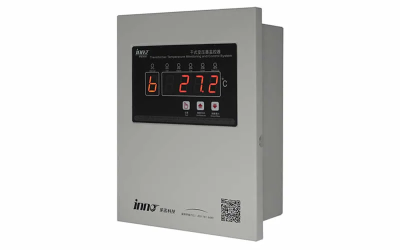
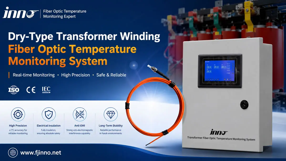
Cast resin and VPI dry-type transformers have higher insulation class limits (Class F 155 °C, Class H 180 °C), but they cool less effectively and are sensitive to overload. Probes are placed in the LV winding or cooling ducts, with one per phase. Dedicated controllers such as the IB-S201, IB-L201 and IB-Q201 handle fan control and alarms. For a broader view, see dry-type transformer temperature monitoring and the intelligent online health monitoring system for dry-type transformers.
| Item | Oil-Immersed | Dry-Type |
|---|---|---|
| Probe jacket | PTFE / armored, oil resistant | PTFE / polyimide |
| Tank feedthrough | Required, oil-tight | Not required |
| Typical channels | 3–16 | 3–4 |
| Typical alarm setting | 105–115 °C hot spot | 130–150 °C (Class F) |
| Retrofit possible | Winding probes: no; oil probes: yes | Limited, duct probes possible |
8. Alarm Settings, Cooling Control and System Integration
8.1 Typical Alarm Levels
Alarm and trip values should follow the manufacturer's design and the applicable loading guide. The table shows common starting points for oil-immersed transformers with thermally upgraded paper.
| Function | Typical Hot Spot Setting | Action |
|---|---|---|
| Cooling stage 1 | 80–85 °C | Start first fan or pump group |
| Cooling stage 2 | 90–95 °C | Start second group |
| Alarm | 110–120 °C | Alarm to SCADA, operator review |
| Trip | 130–140 °C | Trip or load shedding |
8.2 Integration with Condition Monitoring
Fiber optic hot spot data is most valuable as part of a full monitoring package. It can be combined with partial discharge monitoring, online DGA, bushing monitoring and OLTC monitoring. Together these cover the main transformer failure modes. See our transformer condition monitoring strategy guide and the complete transformer monitoring solution.
8.3 Using Hot Spot Data for Dynamic Loading
With a real hot spot reading, operators can load transformers closer to their true thermal capacity during peaks, emergencies or high renewable output, while tracking accumulated ageing. This often defers capital investment in new units. The fluorescent fiber optic monitoring and control system supports this with trend logging and ageing calculation.
9. Typical Industries and Applications
- Power grid and utilities: transmission and distribution transformers where overload risk is high.
- Power generation: generator step-up transformers running near full load.
- Renewable energy: wind and solar step-up transformers with variable, harmonic-rich loading.
- Substations: see substation transformer monitoring.
- Rail transit: traction transformers with cyclic heavy loads.
- Oil and gas: critical process transformers in harsh environments.
Explore more in power transformer monitoring and transformer insulation monitoring.
10. FAQ
10.1 Can fiber optic sensors be installed in an existing transformer?
Winding hot spot probes are normally installed at the factory. For transformers in service, they can only be added when the active part is removed during a major repair or rewind. Oil temperature probes and external monitoring can be retrofitted more easily.
10.2 How many fiber optic channels does my transformer need?
As a rule of thumb, allow at least one probe per phase on the winding expected to run hottest, plus top oil and one spare. Small units need 3–4 channels, medium units 6–8, and large power transformers 8–16 or more. Final numbers should come from the transformer designer's thermal calculation.
10.3 Do fiber optic probes affect transformer insulation?
No. The probes are fully non-metallic and made from materials compatible with transformer oil and pressboard. They are designed and tested to withstand the dielectric stresses inside the winding without creating partial discharge.
10.4 Do the sensors need periodic calibration?
Fluorescence lifetime sensors measure decay time, which is a physical property of the phosphor. They do not drift with fiber losses or light source ageing and do not need recalibration during normal service.
10.5 How long do fiber optic temperature probes last?
Probes are designed to match the service life of the transformer, typically 25–40 years, when installed correctly and protected from mechanical damage during manufacturing.
10.6 Can the system replace a traditional winding temperature indicator?
It can provide the primary hot spot reading and control functions, but many utilities keep a mechanical winding temperature indicator and oil temperature indicator as independent backup protection.
10.7 What communication protocols are supported?
Standard options include 4–20 mA outputs, dry-contact relays and RS485 Modbus RTU. Ethernet and IEC 61850 are available for digital substations.
Get the Right Fiber Optic Monitoring System for Your Transformer
Choosing probe type, channel count and integration approach at the design stage decides how much value you get from hot spot data over the life of the transformer. Our engineers can review your transformer rating, cooling design and monitoring goals, then recommend a complete configuration from probes to SCADA interface.
- Browse our fiber optic temperature monitoring solutions and transformer temperature monitoring solutions.
- Find application notes and documentation on our support page.
- Check our certificates and learn more about us.
- Contact us today for a free channel configuration and quotation.