Indicateur de température des enroulements (WTI) : principe de fonctionnement, limites et méthodes de surveillance
发布时间:2026年9月29日 10:06:47
- A indicateur de température des enroulements (WTI) estimates the hottest point of a transformer winding by combining oil temperature with a heating element driven by load current.
- It is a thermal image device, so it calculates hot-spot temperature rather than measuring it directly inside the winding.
- The WTI drives alarm, trip and cooling fan contacts, and many models also provide a Pt100 or 4–20 mA output for remote monitoring.
- Typical temperature limits follow IEC 60076-2, IEC 60076-7 and IEEE C57.91, with hot-spot limits generally in the region of 110–120 °C for normal operation.
- Correct calibration of the heater current and winding gradient is what makes a WTI reading trustworthy.
- WTI and oil temperature indicator (OTI) serve different purposes and are normally installed together.
- Capteurs de température à fibre optique measure winding hot-spot temperature directly and complement or replace the thermal image method.
Table des matières
- 1. What Is a Winding Temperature Indicator (WTI) on a Transformer?
- 2. How a Winding Temperature Indicator Works: Thermal Image Principle
- 3. WTI Components: Sensing Bulb, Capillary, Heater, Current Transformer and Contacts
- 4. WTI Temperature Limits, Alarm and Trip Settings
- 5. WTI vs OTI: Winding Temperature Gauge and Oil Temperature Gauge Differences
- 6. Typical WTI Technical Parameters
- 7. Calibration, Installation and Maintenance of Winding Temperature Indicators
- 8. Limitations of the Thermal Image Method
- 9. Direct Winding Temperature Monitoring with Fiber Optic Sensors
- 10. Choosing a Transformer Temperature Monitoring Method
- 11. Frequently Asked Questions (FAQ)
1. What Is a Indicateur de température des enroulements (WTI) on a Power Transformer? Definition and Purpose
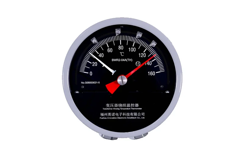
1.1 A winding temperature indicator is a protective and monitoring instrument mounted on oil-immersed power transformers. It shows an estimated winding hot-spot temperature on a dial and operates switch contacts that start cooling fans, raise alarms or trip the transformer.
1.2 Winding temperature is one of the most important operating limits for a transformer because insulation ageing accelerates quickly as temperature rises. Keeping the hot spot within its design limit protects the cellulose insulation and extends service life. For background on how temperature rise affects ratings, see this guide to transformer temperature rise limits and ratings.
1.3 Where the WTI Is Installed
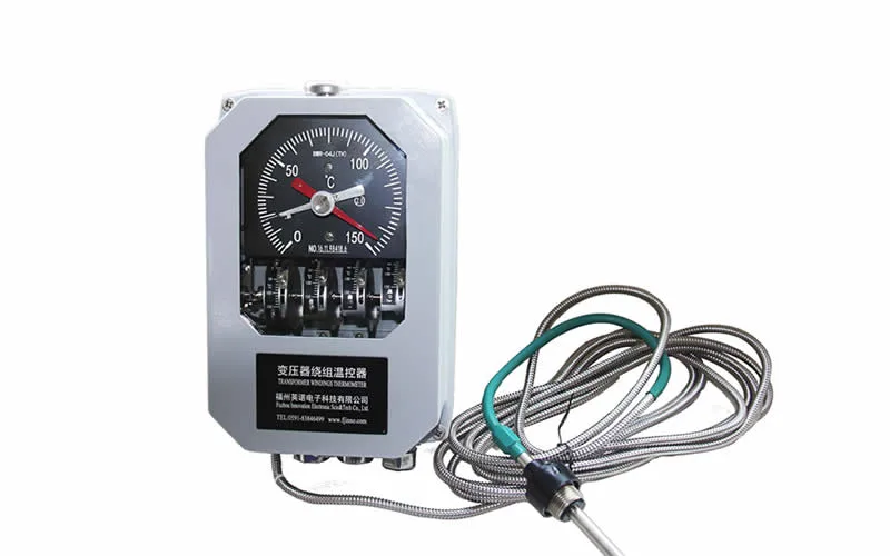
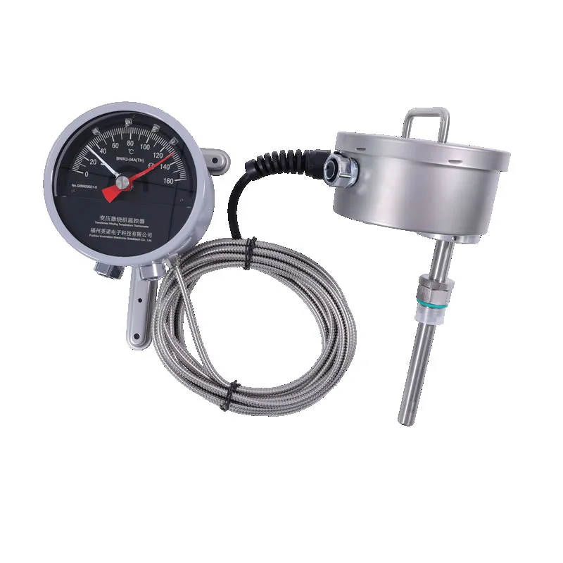
The indicator is usually fitted on the side of the main tank or in the marshalling box at a readable height. Its sensing bulb sits in a thermometer pocket in the tank cover, immersed in the hottest top oil. A typical example is the Indicateur de température des enroulements du transformateur BWR-04/06AJTH.
1.4 Why Winding Hot-Spot Temperature Matters
Persistent overheating shortens insulation life and can lead to gas generation, bubbling and eventual failure. The causes and consequences are explained in this article on transformer overheating causes, symptoms and prevention.
2. How a Indicateur de température des enroulements Works: The Thermal Image Principle and Hot-Spot Calculation
2.1 A WTI does not sit inside the winding. Instead, it reproduces the winding temperature by adding two things together: the temperature of the top oil and an extra temperature rise that represents the gradient between oil and the winding hot spot.
2.2 Step-by-Step Operation
2.2.1 Oil Temperature Sensing
A temperature-sensitive bulb in the oil pocket detects top oil temperature. In a capillary-type instrument, a liquid-filled system transmits the pressure change to a bellows that moves the pointer.
2.2.2 Load-Current Heating
A current transformer (CT) on the winding supplies a current proportional to load to a small heater around the bellows. As load increases, the heater adds more temperature to the pointer.
2.2.3 Resulting Reading
The pointer therefore shows top oil temperature plus the simulated winding-to-oil gradient, giving an estimate of the hot-spot temperature that follows load changes.
2.3 Why the Reading Follows Load
Because the heater responds to current within seconds and the oil responds over hours, the WTI approximates the fast temperature rise of the winding above the slower moving oil. This is the reason it is preferred over a plain oil thermometer for winding protection.
3. WTI Components: Sensing Bulb, Tube capillaire, Élément chauffant, Transformateur de courant et Micro Switches
3.1 A complete winding temperature indication system usually contains the following parts.
3.2 Main Parts
- Sensing bulb: sits in the thermometer pocket and detects oil temperature.
- Capillary tube: a protected tube (often armoured) linking the bulb to the dial.
- Bellows and pointer: convert the temperature signal into pointer movement.
- Heater and matching resistor: produce the load-dependent temperature addition.
- Bushing current transformer: supplies the current proportional to winding load.
- Micro switches or contacts: operate fans, alarm and trip circuits at set temperatures.
- Pt100 or transmitter (optional): provides a remote signal for SCADA or a temperature controller.
3.3 Related Instruments
Newer designs are available in compact form, such as the Indicateur de température des enroulements du transformateur du réacteur BWR2. The oil temperature counterparts are the BWY-802/803A transformer oil temperature indicator and the BWY2 transformer oil temperature indicator.
4. WTI Temperature Limits: Hot-Spot Rise, Alarm Setting, Trip Setting and Cooling Fan Control
4.1 Limits are based on international loading standards. IEC 60076-2 defines temperature-rise limits for design and testing, while IEC 60076-7 and IEEE C57.91 provide loading guides that include hot-spot limits for normal and emergency operation.
| Reference | Paramètre | Typical Value |
|---|---|---|
| IEC 60076-2 | Top-oil temperature rise limit | 60 K |
| IEC 60076-2 | Average winding temperature rise limit | 65 K |
| IEC 60076-2 | Winding hot-spot temperature rise (design reference) | 78 K |
| IEC 60076-7 | Hot-spot limit, normal cyclic loading | 120 °C |
| IEC 60076-7 | Hot-spot limit, long-term emergency loading | 140 °C |
| IEEE C57.91 | Hot-spot reference for normal life expectancy | 110 °C |
4.2 Typical Contact Settings
Set points vary with transformer design, insulation class and manufacturer instructions. The table below shows a typical arrangement; always follow the transformer nameplate and factory test report for your unit.
| Contact Function | Typical Setting Range | Action |
|---|---|---|
| Fan start (stage 1) | Around 70–85 °C | Starts cooling fans |
| Fan stop | Set below fan start with a differential | Stops fans when cooled |
| Alarme | Around 95–110 °C | Sends warning to control room |
| Trip | Around 110–125 °C | Trips the transformer breaker |
4.3 Practical Guidance
Keep fan start settings low enough to hold the hot spot well below the alarm point. Apply a differential on each contact to prevent chattering. Review settings after any change in cooling equipment or transformer rating.
5. WTI vs OTI: Winding Temperature Gauge et Oil Temperature Gauge Key Differences
5.1 Most transformers carry both instruments. The oil temperature indicator reports the top oil temperature, while the WTI estimates the hotter winding condition. They are complementary, not interchangeable.
| Article | WTI (Winding Temperature Indicator) | OTI (Oil Temperature Indicator) |
|---|---|---|
| Measured quantity | Estimated winding hot-spot temperature | Température maximale de l'huile |
| Uses load current | Yes, through CT and heater | Non |
| Response to load change | Fast | Slow |
| Main use | Winding protection and fan control | Oil overheating alarm and trip |
| Typical alarm level | Higher (hot-spot based) | Lower (oil based) |
5.2 Selecting the Right Instrument
For a detailed comparison and selection advice, read transformer oil temperature gauge vs winding temperature gauge. Wider oil monitoring options are covered in transformer oil temperature, level and pressure monitoring systems.
6. Typical WTI Technical Parameters: Measuring Range, Accuracy, Contacts and Output Signals
6.1 The table below lists typical specification values for capillary-type winding temperature indicators. Confirm exact values against the datasheet of the model you select.
| Paramètre | Typical Specification |
|---|---|
| Measuring range | 0–150 °C (other ranges available) |
| Accuracy class | 1.5 or 2.5 (percent of span) |
| Sensing element | Liquid-filled bulb with capillary |
| Longueur capillaire | Commonly 2 m to 20 m, depending on model |
| Number of contacts | Typically 4 adjustable switch contacts |
| Contact rating | AC 250 V / 5 A or DC 220 V / 0.5 A (typical) |
| Heater current input | Matched to CT secondary, commonly 0–2 A or 0–5 A |
| Remote signal (optional) | Pt100 or 4–20 mA transmitter |
| Ambient operating temperature | −40 °C to +55 °C |
| Indice de protection | IP55 (typical) |
6.2 Reading the Specification
Accuracy is quoted as a percentage of the full scale, so a 0–150 °C instrument with class 1.5 can deviate by about ±2.25 °C. The contact setting range and the differential should be checked when planning fan and alarm logic.
7. WTI Calibration, Installation and Maintenance: Heater Current, Winding Gradient and Testing
7.1 A winding temperature indicator is only as accurate as its calibration. The heater current must match the winding-to-oil gradient stated in the transformer factory heat run test report.
7.2 Calibration Steps
- Obtain the winding gradient and CT ratio from the heat run test report.
- Select the matching resistor or tap so the heater adds the correct temperature rise at rated current.
- Check the dial reading against a reference thermometer in an oil or heating bath.
- Verify each contact operates at its set point and resets correctly.
- Record the results in the maintenance log.
7.3 Installation Notes
7.3.1 Capillary and Pocket
Fill the thermometer pocket with a small amount of transformer oil to improve heat transfer. Route the capillary without sharp bends, keep it clear of hot surfaces and secure it along its length.
7.3.2 CT Wiring
Never open-circuit a live current transformer. Short the CT secondary before disconnecting the heater circuit for maintenance.
7.4 Maintenance Interval
Many operators check the WTI during routine outage inspections, comparing it to the oil temperature indicator, the control room repeat and any independent sensors. Persistent differences between instruments deserve investigation.
8. Limitations of the Thermal Image Method: Indirect Measurement and Hot-Spot Accuracy Concerns
8.1 The thermal image is a model, not a measurement. It assumes that the gradient measured at factory test conditions applies to every operating condition.
8.2 Known Limitations
- The winding gradient may differ when cooling mode, oil flow or ambient conditions change.
- The heater has its own thermal time constant, which may not match the real winding.
- Local hot spots caused by eddy currents or flow restrictions are not represented.
- Incorrect CT ratio or resistor selection shifts the reading.
- Instrument drift and capillary damage can reduce accuracy over time.
8.3 Practical Consequence
For critical or highly loaded units, operators often supplement the WTI with a direct measurement so that alarms rest on a real winding temperature. See this guide to transformer winding hot-spot temperature measurement and monitoring sensors.
9. Direct Winding Temperature Monitoring with Capteurs de température à fibre optique et Multi-Channel Demodulators
9.1 Fiber optic sensors are installed in the winding during manufacture and measure temperature at the hot spot itself. They are non-conductive, immune to electromagnetic interference and suited to the high-voltage environment inside a transformer. A full overview is available in fiber optic temperature measurement in transformers.
9.2 Sensor and Instrument Options
9.2.1 Probes and Cables
Le fiber optic temperature sensor for transformer winding hot spot monitoring is designed for direct winding installation. For oil-immersed units, see the capteur de température à fibre optique blindé pour les enroulements de transformateurs à huile and the polyimide fiber optic temperature sensor for transformer windings. Details on probe types are in fluorescent fiber optic temperature sensor probes.
9.2.2 Signal Processing and Systems
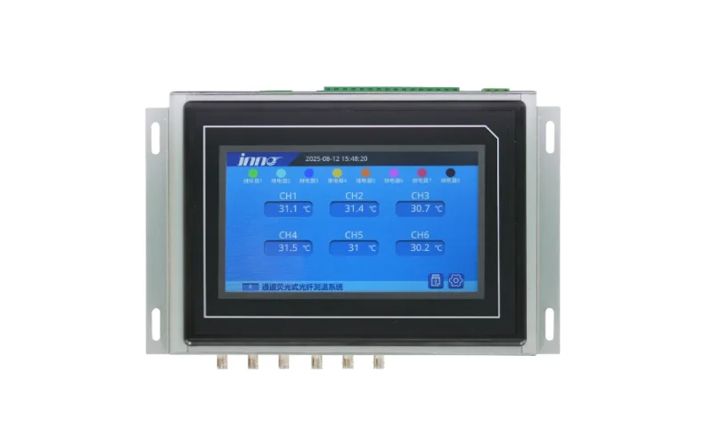
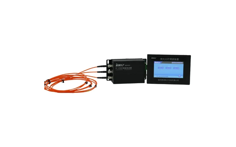
A Transmetteur de température à fibre optique à 3 canaux pour la surveillance des enroulements des transformateurs de puissance converts the optical signal into outputs for alarms and SCADA. For a complete system, review the fiber optic temperature measurement system for oil-immersed transformers.
9.3 Dry-Type Transformers
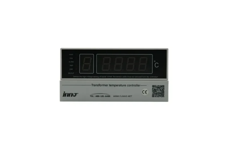
Dry-type units use a different approach because there is no oil. See dry-type transformer temperature monitoring and the IB-S201 dry-type transformer temperature monitor and controller.
10. Choosing a Surveillance de la température des transformateurs Method: WTI, OTI, Fiber Optic and Online Systems Compared
10.1 The right combination depends on transformer size, voltage level, criticality and whether the winding can be fitted with sensors during manufacture.
| Méthode | What It Measures | Best For | Main Limitation |
|---|---|---|---|
| Winding temperature indicator (WTI) | Calculated hot-spot temperature | Standard protection and fan control | Indirect, depends on calibration |
| Oil temperature indicator (OTI) | Température maximale de l'huile | Oil overheating alarm and trip | Slow response to load changes |
| Fiber optic sensor | Direct winding hot-spot temperature | Critical, large or heavily loaded units | Installed during manufacture |
| Online monitoring system | Multiple parameters with trending | Condition-based maintenance programs | Requires integration and data review |
10.2 System-Level Monitoring
Temperature data is most valuable alongside gas, partial discharge and bushing information. Explore the surveillance de la température des transformateurs solution, surveillance des points chauds dans les enroulements des transformateurs et oil-immersed transformer monitoring. For a broader plan, read about transformer condition monitoring methods and strategy.
10.3 Talk to an Engineer
If you need help matching an instrument to a specific transformer, please contact us with the rating, voltage and cooling type.
11. Frequently Asked Questions (FAQ) about Winding Temperature Indicators et Température des enroulements d'un transformateur
1. What does a winding temperature indicator do?
It displays an estimated winding hot-spot temperature and operates contacts that control cooling fans and trigger alarm and trip signals.
2. How does a WTI measure winding temperature?
It adds a load-dependent temperature rise, produced by a heater fed from a current transformer, to the measured top oil temperature. The sum represents the winding hot-spot temperature.
3. Is a WTI a direct measurement of winding temperature?
No. It is a thermal image, which is a calculated estimate. Direct measurement requires sensors such as fiber optic probes installed in the winding.
4. What is the normal operating temperature of a transformer winding?
It depends on load and ambient conditions. Loading guides such as IEC 60076-7 and IEEE C57.91 use hot-spot reference values around 110–120 °C for normal operation.
5. What is the difference between WTI and OTI?
The OTI reads top oil temperature only, while the WTI adds the load-based winding gradient. The WTI therefore reacts faster to load changes and reads higher than the oil temperature.
6. What are typical alarm and trip settings on a WTI?
Alarm settings are often in the 95–110 °C range and trip settings in the 110–125 °C range, but the transformer manufacturer's instructions take priority.
7. How is a winding temperature indicator calibrated?
The heater current is matched to the winding gradient from the heat run test, and the dial and contacts are then checked against a reference thermometer in a temperature bath.
8. Why does my WTI read much higher than the OTI?
The difference is the winding-to-oil gradient added by the heater. The gap grows as load current rises, which is normal behavior.
9. Can a WTI be used on dry-type transformers?
Oil-based WTIs are not used on dry-type units. These transformers use embedded Pt100 or fiber optic sensors connected to a dedicated temperature controller.
10. When should fiber optic winding temperature sensors be used?
They are recommended for large, critical or heavily loaded transformers where a direct, reliable hot-spot measurement supports loading decisions and condition-based maintenance.