Monitoreo de transformadores en centros de datos: temperatura, carga, análisis de gases disueltos (DGA) y estrategia de alarmas
Fecha de publicación:9 de octubre de 2026, 16:48:12
- Data center transformer monitoring protects the power chain that feeds UPS systems, cooling plant and IT loads, where an unplanned transformer outage can interrupt an entire hall.
- Most in-building data center transformers are dry-type or cast resin units, so winding temperature, cooling fan control y load tracking are the first priorities.
- Oil-filled units serving the utility side or outdoor yards benefit from online dissolved gas analysis (DGA) that tracks seven fault gases without taking the transformer out of service.
- Non-linear UPS and server loads create harmonic heating, so loading data must be read together with temperature data.
- A tiered alarm strategy (advisory, warning, critical, trip) keeps operators focused and prevents nuisance alarms.
- Monitoring devices should speak Modbus RTU/TCP, IEC 61850 or 4–20 mA so alarms reach the BMS, EPMS, DCIM or SCADA already in use.
- Product parameters in this guide are taken from INNOFZ product pages for Pt100 controllers, fiber optic temperature systems and online DGA monitors.
Índice
- 1. Why Data Center Transformers Need Dedicated Condition Monitoring
- 2. Transformer Types in Data Centers: Dry-Type, Cast Resin and Oil-Immersed
- 3. What to Monitor: Priority Parameters for Data Center Transformers
- 4. Temperature Monitoring: Pt100 Controllers and Fiber Optic Winding Sensors
- 5. Load Monitoring: Loading Level, Harmonics and Redundancy
- 6. DGA Monitoring for Oil-Filled Data Center Transformers
- 7. Health Monitoring for Dry-Type Transformers: Partial Discharge, Vibration and Environment
- 8. Alarm Strategy: Tiers, Thresholds, Fan Control and Escalation
- 9. Integration with BMS, EPMS, DCIM and SCADA: Protocols and Data Flow
- 10. Selection Guide: Matching Monitoring Equipment to Transformer Type
- 11. Commissioning, Testing and Maintenance
- 12. Preguntas frecuentes (FAQ)
1. Why Data Center Transformer Monitoring Matters: Uptime, Power Distribution and Thermal Risk
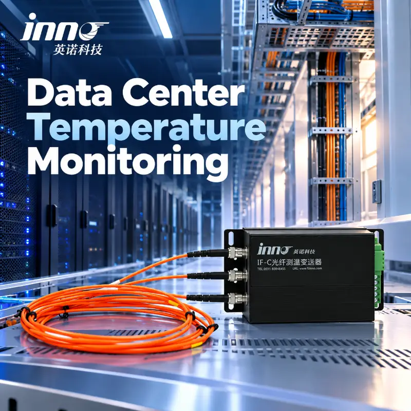
1.1 A data center transformer sits at the head of the electrical distribution chain. It steps medium voltage down to the level used by switchboards, UPS systems, chillers and server halls. When it trips or fails, the effect reaches every downstream system at once, which is why operators treat these assets as critical.
1.2 Transformers in data centers face a demanding duty. Loads are high and continuous, cooling failures are common to the entire plant, and load patterns change as new server capacity is energised. Monitoring turns hidden thermal and insulation changes into data that operators can act on before an outage. For a general overview of the available modules, see the monitoreo de transformadores solución.
1.3 Typical Failure Pathways
Most transformer problems start slowly: sustained overheating from overload or harmonics, restricted cooling air, insulation ageing, moisture, partial discharge or loose connections. These conditions show up in temperature, load and gas data well before a protection trip. The causes and detection methods are covered in this guide to modos de falla de los transformadores.
1.4 Monitoring versus Protection
Protection relays clear faults within milliseconds. Monitoring watches slower changes and gives maintenance teams time to schedule work during planned windows. A good temperature controller does both by providing local fan control, alarm and trip contacts alongside communication to upper-level systems.
2. Transformer Types in Data Centers: Dry-Type, Cast Resin y Oil-Immersed Units
2.1 The transformer type decides which sensors make sense. Dry-type and cast resin units are widely used inside buildings because they avoid oil handling and reduce fire load. Oil-immersed units are common where larger ratings, outdoor installation or utility-owned equipment are involved.
| Tipo de transformador | Typical Data Center Location | Primary Monitoring Focus |
|---|---|---|
| Dry-type / cast resin | Indoor electrical rooms, floor-level distribution | Winding temperature, fan control, load, partial discharge, environment |
| Oil-immersed (distribution class) | Outdoor yard, utility intake, campus substation | Winding and oil temperature, DGA, oil level and pressure, load |
| Oil-immersed (power class) | Dedicated campus substation | Fiber optic hot spot, DGA, partial discharge, bushings, OLTC |
2.2 Related Application Pages
Ver monitoreo de la temperatura de los transformadores de tipo seco, monitoreo de transformadores sumergidos en aceite y monitoreo de transformadores de potencia for typical configurations.
3. What to Monitor: Priority Parameters for Data Center Monitoreo del estado de los transformadores
3.1 Start with the parameters that give the best protection per unit of cost, then add layers for higher-risk assets.
| Priority | Parámetro | Applies To | Por qué es importante |
|---|---|---|---|
| 1 | Winding temperature (three phases) | Dry-type and oil-immersed | Sets insulation ageing rate and trip protection |
| 1 | Cooling fan status and control | Dry-type | Confirms forced-air cooling is working |
| 2 | Load current and loading percentage | All | Explains thermal behavior and redundancy margin |
| 2 | Room or enclosure temperature | Dry-type | Ambient rise reduces loading capability |
| 3 | Dissolved gases in oil | Oil-immersed | Early warning of overheating, discharge and arcing |
| 3 | Partial discharge, vibration, arc light | Dry-type and oil-immersed | Early signs of insulation or connection defects |
| 4 | Oil level, pressure and temperature | Oil-immersed | Detects leaks and internal pressure events |
3.2 Building a Monitoring Plan
A broader framework for selecting parameters is described in transformer condition monitoring methods, parameters and strategy.
4. Monitoreo de la temperatura: Pt100 Temperature Controllers y Fiber Optic Winding Sensors
4.1 Winding temperature is the most important single measurement on a data center transformer. Two approaches are common: Pt100 sensors embedded in the winding with a temperature controller, and fluorescent fiber optic probes with a multi-channel transmitter.
4.2 Pt100 Controllers for Dry-Type and Cast Resin Transformers
4.2.1 YN-XP502F-3T Intelligent Monitoring Device
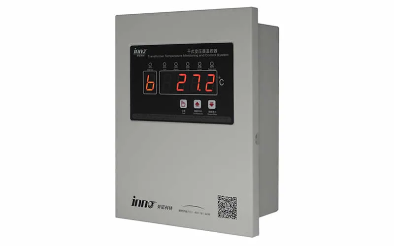
El Dispositivo de monitoreo inteligente para transformadores de tipo seco YN-XP502F-3T monitors three Pt100 winding channels, controls cooling fans and provides alarm and trip outputs with Modbus RTU communication. Its product page lists data center transformer systems among its typical applications.
| Parámetro | YN-XP502F-3T Specification |
|---|---|
| Temperature sensor | Pt100, 3-channel winding temperature |
| Rango de medición | −30.0 °C to 240.0 °C |
| Measurement accuracy | ±1% FS (controller class 0.5, sensor class B) |
| Resolución | 0.1 °C |
| Pantalla | 2.8-inch color LCD touch screen |
| Fuente de alimentación | AC/DC 24–240 V, ≤ 10 W |
| Control contact capacity | 16 A / 250 VAC |
| Comunicación | Modbus RTU, address 1–247, 1200–38400 bps (default 9600 bps), parity none/odd/even |
| Operating temperature | −25 °C to +55 °C |
| Dimensions / panel cutout | 96 × 96 × 84 mm / 90 × 90 mm |
| Records | Historical temperatures, maximum values and event records with time information |
4.2.2 Factory Default Control Settings
The thresholds below are the factory default values listed for the YN-XP502F-3T. They are adjustable during commissioning and should always be set to the transformer manufacturer's values for the insulation class in use.
| Código | Función | Setting Range | Factory Default |
|---|---|---|---|
| C1 | Fan stop temperature | 0.0 °C to 185.0 °C | 85.0 °C |
| C2 | Fan start temperature | C1 + 5.0 °C to 190.0 °C | 100.0 °C |
| C3 | Winding over-temperature alarm | C2 + 5.0 °C to 195.0 °C | 130.0 °C |
| C4 | Winding over-temperature trip | C3 + 5.0 °C to 200.0 °C | 150.0 °C |
4.2.3 IB-S201 Temperature Monitor and Controller
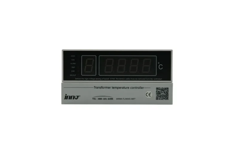
For cabinet-panel installations, the Monitor y controlador de temperatura para transformadores de tipo seco IB-S201 provides Pt100 input, three-phase display with maximum value indication, fan control, alarm and trip outputs. Optional 4–20 mA, RS485 or RS232 output supports connection to SCADA or BMS. Further options in the same family include the IB-L201 y IB-Q201 controllers.
| Parámetro | IB-S201 Specification |
|---|---|
| Rango de temperatura | −30.0 °C to +240.0 °C |
| Measurement accuracy | ±1% FS (thermostat level 0.5, sensor class B) |
| Resolución | 0.1 °C |
| Working voltage | AC 220 V, +10% / −15%, 50 or 60 Hz ±2 Hz |
| Fan output capacity | 5 A / 250 VAC |
| Control output capacity | 5 A / 250 VAC; 5 A / 30 VDC resistive |
| Power dissipation | ≤ 8 W |
| Temperatura ambiente | −20 °C to +55 °C |
| Dimensions / opening | 160 × 80 × 120 mm / 153 × 77 mm |
| Optional outputs | 4–20 mA, RS485 / RS232, ambient and core temperature inputs |
4.3 Fiber Optic Temperature Systems
4.3.1 When Fiber Optic Is the Better Choice
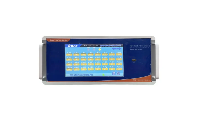
Fiber optic probes measure the winding hot spot directly, are electrically isolated and are unaffected by electromagnetic interference. They suit larger or higher-voltage transformers, units with many measurement points and projects where direct hot-spot data is needed. The sistema multicanal de medición y monitoreo de temperatura por fibra óptica is configured for transformers, switchgear, busbars and cable terminals.
| Parámetro | Multi-Channel Fiber Optic System Specification |
|---|---|
| Tipo de medición | Medición óptica de temperatura de tipo puntual |
| Rango de temperatura | −40 °C to +240 °C (higher range customizable) |
| Accuracy / resolution | ±1 °C standard / 0.1 °C |
| Cantidad de canales | De 1 a 64 canales, personalizable |
| Tipo de fibra | Fibra óptica de cuarzo |
| Diámetro de la sonda | 2,5 mm estándar; tamaños más pequeños personalizables |
| Opción de sonda de alta tensión | Sonda de clase de 100 kV disponible |
| Fuente de alimentación | AC/DC 220 V (other inputs depending on configuration) |
| Comunicación | RS485, Modbus; 4–20 mA optional |
| Installation | Panel mount, cabinet mount, DIN rail or project-specific |
4.3.2 Related Fiber Optic Products
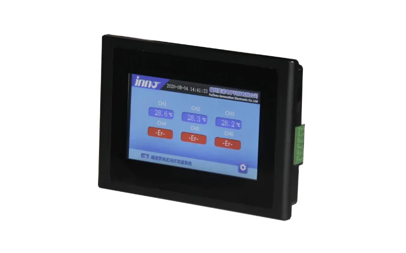
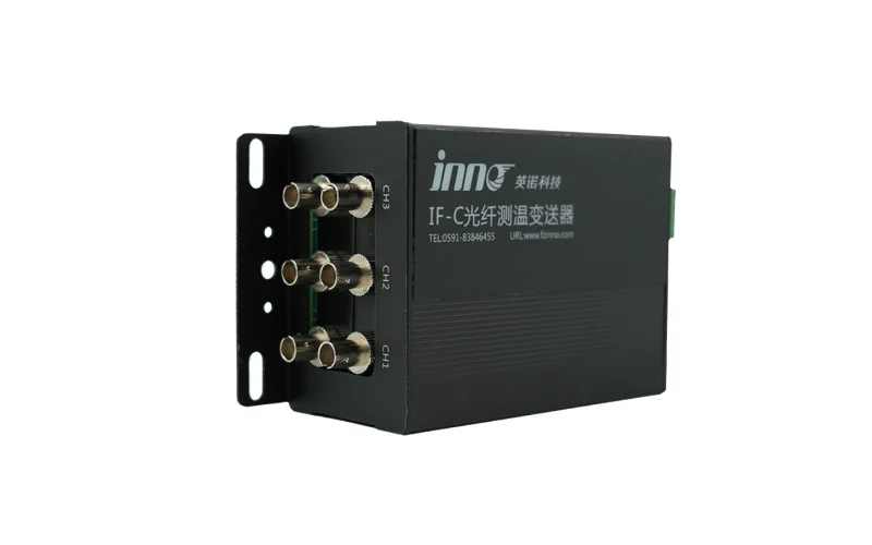
Smaller channel counts are served by the IF-G3 3-channel fiber optic temperature sensing module y el 6-channel fluorescent fiber optic temperature demodulator, while larger projects can use the Sistema de medición de temperatura por fibra óptica fluorescente de 64 canales. Local readout is available through the host con pantalla de temperatura de fibra óptica integrada. For probe options see the fiber optic temperature sensor for transformer winding hot spot monitoring, and for the principle read fiber optic temperature measurement in transformers.
4.4 Oil-Immersed Unit Instruments
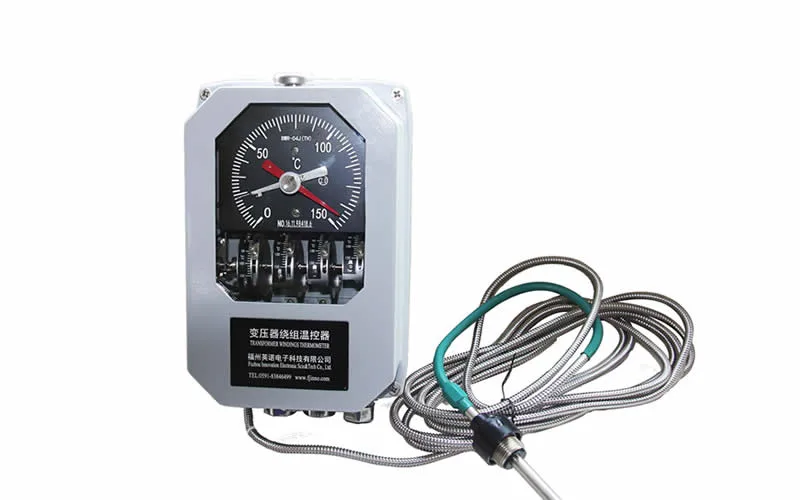
Oil-filled transformers can also use mechanical indicators and oil-system monitoring: the Indicador de temperatura del devanado del BWR2, the BWY2 oil temperature indicator y el sistema de monitoreo de la temperatura, el nivel y la presión del aceite de los transformadores. How the winding indicator works is explained in this winding temperature indicator guide.
5. Load Monitoring: Loading Level, Harmonic Heating, K-Factor and N+1 Redundancy
5.1 Winding temperature only makes sense when it is read together with load. A transformer running hot at light load points to a cooling or insulation problem, while a transformer running hot at heavy load may simply be near its design limit.
5.2 Why Data Center Loads Are Demanding
- Continuous high loading: server and cooling loads run around the clock, leaving little cool-down time.
- Harmonic currents: UPS rectifiers and switch-mode power supplies add harmonic content that increases winding and stray losses. IEEE C57.110 describes how to derate transformers for non-sinusoidal loads, and K-factor rated designs are available for harmonic-rich duty.
- Redundancia: in N+1 or 2N designs, the surviving transformer must carry the load of a failed unit, so normal loading should leave headroom for that case.
- Growth: loading rises as halls are filled, so trends matter more than single readings.
5.3 Where Load Data Comes From
Load current, power and harmonic distortion are typically captured by the electrical power monitoring system (EPMS) or power meters on the transformer secondary. This data is combined with temperature values in the BMS, DCIM or SCADA platform. Temperature controllers such as the YN-XP502F-3T and IB-S201 supply the thermal side through Modbus RTU or analog output.
5.4 Useful Load Indicators
| Indicator | What It Shows | How to Use It |
|---|---|---|
| Loading percentage of rating | Utilisation relative to nameplate | Track against the design planning limit and redundancy case |
| Peak versus average load | Load profile shape | Spot short peaks that drive hot-spot temperature |
| Total harmonic distortion of current | Non-linear load content | Raise derating or K-factor questions early |
| Load versus winding temperature | Thermal response | Flag temperature that does not follow load |
| Loss of redundancy flag | Surviving units carrying extra load | Escalate alarm priority while the condition lasts |
6. Monitoreo de la DGA for Oil-Filled Data Center Transformers: Seven Fault Gases, IEC 61850 and Hot-Oil Installation
6.1 Dissolved gas analysis is the most sensitive way to detect incipient faults in oil-immersed transformers. For data center campuses with oil-filled units in the yard or substation, an online monitor removes the delay of laboratory sampling. See Monitoreo en línea de gases disueltos (DGA) en transformadores for guidance on when it is justified and online DGA vs oil sampling for a comparison.
6.2 Online DGA Monitor Specifications
El sistema de monitoreo en línea del análisis de gases disueltos (DGA) para aceite de transformador uses dynamic vacuum membrane degassing and gas chromatography with TCD and FID detectors. The detection ranges below are those published for the system.
| Gas Component | Detection Range | Precisión | Repeatability (RSD) |
|---|---|---|---|
| Hidrógeno (H₂) | 2 – 2,000 μL/L | ± 30% or ± 5 μL/L | ≤ 5% |
| Metano (CH₄) | 0.5 – 2,000 μL/L | ± 30% or ± 1 μL/L | ≤ 5% |
| Etano (C₂H₆) | 0.5 – 2,000 μL/L | ± 30% or ± 1 μL/L | ≤ 5% |
| Etileno (C₂H₄) | 0.5 – 2,000 μL/L | ± 30% or ± 1 μL/L | ≤ 5% |
| Acetileno (C₂H₂) | 0.1 – 500 μL/L | ± 30% or ± 0.5 μL/L | ≤ 5% |
| Carbon monoxide (CO) | 5 – 5,000 μL/L | ± 30% or ± 10 μL/L | ≤ 5% |
| Carbon dioxide (CO2) | 10 – 10,000 μL/L | ± 30% or ± 20 μL/L | ≤ 5% |
| Moisture in oil (optional) | 1 – 100 μL/L | ± 15% | ≤ 5% |
6.3 System Operating Parameters
| Parámetro | Especificaciones |
|---|---|
| Ciclo de muestreo y análisis | Adjustable, minimum ≤ 2 hours |
| Gas extraction method | Dynamic vacuum membrane degassing |
| Método de análisis | Gas chromatography with TCD / FID detectors |
| Gas portador | Nitrógeno de alta pureza (generador en el lugar opcional) |
| Almacenamiento de datos | ≥ 10 years of on-board records |
| Comunicación | RS-485 (Modbus RTU/TCP), IEC 61850, Ethernet RJ-45; 4–20 mA opcional |
| Fuente de alimentación | AC 220 V ± 15%, 50/60 Hz; ≤ 200 W |
| Ingress protection | IP55 |
| Operating temperature | −20 °C to +55 °C |
| Relative humidity | ≤ 95% RH, non-condensing |
| Installation | Energized transformer; oil inlet and outlet valve connection only |
6.4 Reading the Gas Data
6.4.1 Interpretation Methods
Interpretation follows IEC 60599 and IEEE C57.104 principles: absolute concentrations, gas ratios, the Duval Triangle and the rate of gas increase. A rapidly rising value deserves more attention than a stable, higher one. Learn more on the análisis de gases disueltos solution page.
6.4.2 What Each Gas Points To
| Gas Pattern | Likely Condition | Suggested Follow-Up |
|---|---|---|
| Hydrogen rising, with methane | Partial discharge or low-energy activity | Resample, check PD data |
| Ethylene and ethane rising | Thermal fault in oil | Compare with winding temperature and load |
| Acetylene appearing | Arcing or very high temperature | Shorten sampling, plan inspection, consider load reduction |
| CO and CO2 rising | Cellulose insulation stress | Review loading history and cooling |
7. Health Monitoring for Dry-Type Transformers: Descarga parcial, Vibración, Arc Light and Environment
7.1 Temperature alone does not reveal every dry-type problem. Partial discharge, loose connections and environmental conditions such as humidity also affect reliability. The sistema inteligente de monitoreo en línea del estado de los transformadores de tipo seco combines several of these signals on one platform.
7.2 What the System Covers
- Winding and iron core temperature through a fluorescent fiber optic temperature controller.
- Partial discharge monitoring through UHF and high-frequency current sensors.
- Electrical connection point arc-light monitoring.
- Transformer vibration, ground vibration and environmental noise.
- Room temperature and humidity, with local control of fans, heating and dehumidification.
- Health status assessment with warning notification to operators.
7.3 Published Technical Parameters
| Parámetro | Especificaciones |
|---|---|
| Power input | AC 220 V, power consumption ≤ 50 W |
| Analog input | 4–20 mA / 0–5 V / 0–10 V DC acquisition |
| Switching input | Señal de entrada de contacto seco |
| Switching output | Relay output via high-current contactor, contact capacity ≥ AC 220 V / 10 A |
| Serial communication | Interfaz RS485 |
| Ethernet port | RJ45 |
| Optical interface | IEC 61850 protocol conversion, fiber optic interface |
| Slave device power output | 24 V / 30 W, 12 V / 20 W |
7.4 Partial Discharge for Oil-Filled Units
For oil-immersed transformers, see the sistema de monitoreo en línea de descargas parciales en transformadores and the guide to partial discharge monitoring in transformers. Bushing and tap changer condition are covered by the sistema de monitoreo de bujes y el OLTC online monitoring system.
8. Alarm Strategy for Data Center Transformers: Tiered Thresholds, Fan Control, Correlation and Escalation
8.1 Data center operations teams manage thousands of points. Transformer alarms must be few, meaningful and tied to a clear action. A tiered structure with local protection and remote supervision works well.
8.2 Four-Tier Alarm Structure
| Tier | Temperature Example | Load Example | DGA Example | Response |
|---|---|---|---|---|
| Advisory | Drift from normal temperature-versus-load relationship | Sustained loading above planning limit | Slow upward gas trend | Log, review at next inspection |
| Warning | Fan start reached or fan fault | Loading approaching nameplate or redundancy reduced | Rising rate of hydrogen or hydrocarbons | Check cooling, load transfer, shorten sampling |
| Critical | Winding over-temperature alarm | Loading above nameplate | Acetylene appearance or fast gas increase | Reduce load, dispatch inspection, plan outage |
| Viaje | Winding over-temperature trip | Protection relay operation | Handled by protection relays | Automatic isolation, switch to redundant path |
8.3 Temperature Threshold Logic
8.3.1 Fan Start, Alarm and Trip
Use four separate thresholds: fan stop, fan start, alarm and trip. The YN-XP502F-3T requires each higher threshold to be at least 5.0 °C above the previous one, which prevents overlapping settings. Base the values on the transformer insulation class: IEC 60076-11 lists average winding temperature rise limits of 100 K for class F and 125 K for class H dry-type insulation systems, and the controller defaults listed in section 4.2.2 must be aligned with the manufacturer's data.
8.3.2 Fan Exercise and Fault Alarms
Scheduled fan operation keeps fans ready for the next load peak. The YN-XP502F-3T supports scheduled fan run time of 1–100 minutes at intervals of 1–100 hours, and indicates sensor and device faults so a failed probe is not mistaken for a normal reading.
8.4 Cross-Parameter Rules
- High temperature with normal load and working fans: possible internal heating or sensor error.
- High temperature with high harmonic content: review derating and cooling margin.
- Rising hydrogen with rising partial discharge: likely insulation defect, escalate.
- Temperature rising while redundancy is reduced: raise priority because the surviving unit carries extra load.
8.5 Reducing Nuisance Alarms
Apply a deadband so alarms clear only after the value falls below the trigger point, add a short delay for non-trip alarms, and keep trip logic local on relay contacts so protection never depends on the network.
9. Integration with BMS, EPMS, DCIM y SCADA: Protocols, Outputs and Data Flow
9.1 Transformer data is most useful when it appears on the same screens that operators already use. The table summarises communication options published for the products discussed above.
| Producto | Communication and Output Options |
|---|---|
| YN-XP502F-3T | Modbus RTU; relay contacts 16 A / 250 VAC for fan, alarm, trip |
| IB-S201 | Opcional: 4–20 mA, RS485 o RS232; salidas para ventilador, alarma y desconexión |
| Multi-channel fiber optic system | RS485 Modbus; optional 4–20 mA; alarm output |
| Monitor en línea de la DGA | RS-485 (Modbus RTU/TCP), IEC 61850, Ethernet RJ-45; 4–20 mA opcional |
| Sistema de monitoreo de estado de tipo seco | RS485, RJ45 Ethernet, interfaz de fibra óptica IEC 61850; entradas analógicas y de contacto seco |
9.2 Typical Data Flow
- Sensors and controllers measure temperature, gas or discharge activity at the transformer.
- Local relays handle fan, alarm and trip actions.
- Modbus, IEC 61850 or analog signals carry values to a gateway or controller.
- The BMS, EPMS or DCIM platform stores the data, shows trends and sends notifications.
- Operators combine thermal data with load and cooling data for decisions.
9.3 Integration Tips
Request the register map before design, confirm baud rate and parity, keep RS485 wiring in a daisy chain with termination at each end, and test every alarm point from sensor to screen. For wiring and system design questions, visit the support página.
10. Guía de selección: Matching Monitoring Equipment to Data Center Transformer Type and Criticality
| Situation | Recommended Starting Point | Add When Risk Is Higher |
|---|---|---|
| Indoor dry-type or cast resin transformer | YN-XP502F-3T or IB-S201 Pt100 controller with Modbus or 4–20 mA output | Dry-type health monitoring system; fiber optic temperature channels |
| Retrofit of an existing controller | YN-XP502F-3T (confirm wiring, panel cutout and contact logic first) | Upgrade communication to the BMS or SCADA |
| Oil-immersed distribution transformer | Winding and oil temperature indicators, oil level and pressure monitoring | Monitor en línea de la DGA |
| Large or critical oil-immersed transformer | Fiber optic winding sensors and online DGA | Partial discharge, bushing and OLTC monitoring |
| Multiple transformers in one campus | Common protocol (Modbus or IEC 61850) across all devices | Central dashboard with fleet-level alarm list |
10.2 Questions to Settle Before Ordering
- Is the transformer dry-type, cast resin or oil-immersed, and what is its insulation class?
- How many winding temperature points are required, and which sensor type (Pt100 or fiber optic)?
- Which protocol does the BMS, EPMS, DCIM or SCADA accept?
- What are the panel cutout, supply voltage and relay contact requirements?
- Can sensors be built in during manufacture, or is this a retrofit?
10.3 Talk to an Engineer
Send the transformer type, rating, insulation class and communication requirement through contact us for a configuration proposal. You can also review our certificates and learn more about us.
11. Commissioning, Alarm Testing and Maintenance of Transformer Monitoring Systems
11.1 A monitoring system delivers value only when its alarms have been tested and its settings are documented.
11.2 Commissioning Checklist
- Verify each sensor reading against a reference value.
- Enter fan start, fan stop, alarm and trip temperatures from the transformer manufacturer's data.
- Test fan, alarm and trip contacts with simulated values.
- Confirm Modbus addresses, scaling and units on the BMS or SCADA screens.
- Record settings, wiring and register maps in the asset file.
11.3 Routine Maintenance
11.3.1 Temperature Controllers
Check sensor wiring, compare displayed phase temperatures, exercise the fans and review the event record after any alarm.
11.3.2 Online DGA Monitors
Follow the manufacturer's schedule for carrier gas, calibration and consumables, and cross-check results against a laboratory sample from time to time.
11.4 Review Alarm Statistics
Review alarm counts every few months. Frequent advisory alarms may indicate thresholds set too tight, while no alarms at all across a large fleet may deserve a test of the notification path.
12. Frequently Asked Questions (FAQ) about Data Center Transformer Monitoring
1. What should be monitored on a data center transformer?
At minimum, three-phase winding temperature, cooling fan status and load. Oil-filled units should add online DGA, and critical units can add partial discharge, vibration and environmental monitoring.
2. Why is temperature monitoring so important for data center transformers?
Data center loads are high and continuous, so winding temperature is the main driver of insulation ageing and the most direct indicator of thermal stress or cooling problems.
3. How many temperature channels does a dry-type transformer controller need?
Three channels are standard, one for each phase winding. The YN-XP502F-3T provides three Pt100 channels, and the IB-S201 monitors three winding points and displays the maximum value.
4. Can a transformer temperature controller connect to a BMS or SCADA system?
Yes. The YN-XP502F-3T supports Modbus RTU, and the IB-S201 offers optional 4–20 mA, RS485 or RS232 output for remote monitoring.
5. What is the difference between Pt100 and fiber optic temperature sensing?
Pt100 sensors are embedded in the winding and read by a temperature controller, which is cost-effective for dry-type units. Fiber optic probes measure the hot spot directly, are electrically isolated and can support many measurement points, up to 64 channels in the multi-channel system.
6. Do dry-type data center transformers need DGA?
No. DGA applies to oil-filled transformers. Dry-type units rely on temperature, load, partial discharge and environmental monitoring instead.
7. How often does an online DGA monitor report?
The online DGA system described in this guide has an adjustable sampling cycle with a minimum of two hours or less, and it measures seven gases: H2, CH4, C2H6, C2H4, C2H2, CO and CO2.
8. Can an online DGA monitor be installed without a transformer outage?
Yes. The system connects to the oil inlet and outlet valves of an energized transformer, so no outage or oil drainage is required for installation.
9. How do harmonics affect transformer monitoring?
Harmonic currents from UPS and server power supplies add heating beyond what the fundamental current alone would produce. Reading temperature together with load and harmonic data helps identify when derating or cooling improvements are needed.
10. How should alarms be set for data center transformers?
Use four tiers (advisory, warning, critical and trip), base temperature limits on the manufacturer's insulation class data, keep trip logic on local relays and use cross-parameter rules so that load, temperature and gas data confirm one another before an alarm escalates.