What Is a Transformer Alarm?
Fecha de publicación:2026年10月11日 12:42:00
- Transformer alarms warn operators when monitored temperature, dissolved gas, oil, pressure, insulation, bushing, OLTC, cooling or device conditions reach configured limits or abnormal states.
- Warning signals may come from winding temperature, top-oil temperature, DGA, partial discharge, oil level, tank pressure, bushing condition, tap changer operation or auxiliary equipment.
- Alarm and trip functions serve different purposes: alarms normally request assessment, while trip signals are intended to initiate isolation through the protection circuit.
- No universal alarm threshold applies to every transformer. Setpoints depend on transformer design, rating, insulation system, cooling mode, sensor location, manufacturer recommendations and protection philosophy.
- Online condition monitoring adds trend analysis, remote notification and multi-parameter comparison so abnormal signals can be evaluated in operating context.
- SCADA integration can combine relay contacts, measured values, equipment status and communication alarms from multiple monitoring devices.
Índice
- 1. Warning Signals, Alarm Logic and Fault Indications
- 2. Warning vs Alarm vs Trip Protection
- 3. Abnormal Operating Parameters and Condition Indicators
- 4. Winding and Oil Temperature Protection
- 5. DGA Fault Gas Warnings and Trend Analysis
- 6. Partial Discharge and Insulation Condition Alerts
- 7. Oil, Bushing, OLTC and Cooling System Conditions
- 8. Relay Outputs, Remote Monitoring and SCADA Integration
- 9. Alarm Thresholds, Setpoints and Protection Coordination
- 10. Online Condition Monitoring and Early Fault Detection
- 11. Monitoring Devices and Alarm Output Options
- 12. Selecting Monitoring by Transformer Risk
- 13. Transformer Alarm FAQ
1. Warning Signals, Alarm Logic and Fault Indications
1.1 What Does a Transformer Alarm Mean?
Transformer alarms indicate that a measured value, equipment status or monitoring-device condition has reached configured logic that requires attention. Signals can represent abnormal transformer operation, a developing fault, reduced cooling performance, auxiliary equipment malfunction or a problem in the measurement chain.
Alarm indication alone does not prove that internal failure has occurred. High temperature may result from loading or cooling conditions, while communication-loss signals may come from the monitoring system rather than the transformer. Reliable interpretation therefore combines the affected parameter with load, trend, operating history and related measurements.
1.2 Condition, Equipment and Communication Alerts
- Condition alerts: temperature, gas concentration, oil level, pressure or discharge activity reaches configured criteria.
- Equipment status alerts: fans, pumps, tap changer drives or other auxiliary equipment report abnormal operating states.
- Measurement-chain alerts: sensor failure, probe disconnection, invalid readings or communication loss affect data reliability.
1.3 Common Causes of Abnormal Transformer Signals
Abnormal signals usually originate from thermal stress, electrical activity, oil-system changes, mechanical deterioration, cooling-system problems or instrumentation faults.
- Thermal stress: high loading, reduced cooling or elevated ambient temperature can increase winding and oil temperature.
- Electrical activity: partial discharge, arcing or other internal electrical faults can affect PD and DGA measurements.
- Oil-system changes: leakage, pressure variation, gas accumulation or abnormal oil level can generate warning signals.
- Mechanical condition: OLTC wear, fan failure or pump malfunction can produce equipment-status alarms.
- Instrumentation faults: wiring, sensor or communication problems can create alarms unrelated to transformer health.
2. Warning vs Alarm vs Trip Protection
2.1 Difference Between Warning, Alarm and Trip
Warning, alarm and trip stages represent different levels of response. Warning functions normally identify an early deviation, alarm functions call for operator assessment, and trip signals are intended to initiate protective isolation when connected to the transformer protection circuit.
Actual breaker operation depends on protection logic, wiring and site configuration. Monitoring devices can therefore provide alarm or trip contacts without replacing the dedicated protection system.
| Función | Objetivo principal | Respuesta típica | Automatic Isolation | Typical Examples |
|---|---|---|---|---|
| Warning | Identify early deviation or adverse trend | Review trend and related operating data | No | Increasing gas trend, gradual temperature rise, communication instability |
| Alarma | Identify abnormal condition requiring attention | Verify signal, load, cooling and related measurements | Normally no | High temperature, low oil level, cooling fault, abnormal gas condition |
| Viaje | Initiate protective isolation | Protection circuit operates according to configured logic | When connected and configured for tripping | Temperature trip contact, gas relay trip element, protection relay output |
2.2 Monitoring Devices vs Protection Relays
Online monitoring devices mainly collect measurements, calculate trends and report abnormal conditions. Protection relays and hardwired trip circuits perform rapid isolation when protection criteria are met. Condition monitoring therefore supplements protection rather than replacing it.
3. Abnormal Operating Parameters and Condition Indicators
3.1 Thermal, Chemical and Electrical Indicators
Transformer condition assessment can combine temperature, gas, oil, insulation, bushing, OLTC and cooling information. Each parameter describes a different part of transformer operation, so abnormal values should be evaluated together rather than treated as isolated signals.
| Condition Indicator | Possible Abnormal Signal | What It May Indicate | Typical Monitoring Method |
|---|---|---|---|
| Temperatura del bobinado | High or rapidly increasing temperature | Overload, reduced cooling or local overheating | WTI, embedded sensor or fiber optic probe |
| Temperatura máxima del aceite | Temperature reaches configured level | High load, cooling deterioration or internal heating | OTI or electronic temperature sensor |
| Dissolved Gas | Gas concentration or rate of change becomes abnormal | Thermal, discharge or arcing activity | Monitoreo en línea de DGA |
| Nivel de aceite | Level moves outside expected range | Leakage, volume change or level-measurement problem | Oil level gauge or electronic sensor |
| Tank / Oil Pressure | Pressure changes beyond configured condition | Internal gas generation or oil-system abnormality | Pressure sensor or device contact |
| Descarga parcial | Discharge activity, trend or pattern becomes abnormal | Possible insulation defect or discharge activity | UHF, HFCT or ultrasonic monitoring |
| Estado de los bujes | Electrical characteristics change from baseline | Possible insulation deterioration | Bushing condition monitoring |
| OLTC Condition | Current, vibration, temperature, torque or position changes | Mechanical, thermal or electrical deterioration | OLTC online monitoring |
| Cooling Equipment | Fan or pump failure | Reduced cooling capacity | Status contacts and monitoring inputs |
| Sensor / Communication | Probe break, invalid value or communication loss | Measurement-chain failure | Device self-diagnostics |
3.2 Multi-Parameter Condition Assessment
Continuous monitoreo del estado de los transformadores combines thermal, chemical, electrical and mechanical indicators. Multi-parameter analysis is especially useful when one abnormal reading has several possible causes.
Temperature increase accompanied by cooling failure suggests a different operating condition from temperature increase accompanied by abnormal DGA or partial discharge activity. Related measurements therefore improve fault screening and alarm prioritization.
4. Winding and Oil Temperature Protection
4.1 Winding Temperature Indicators and Hot-Spot Measurement
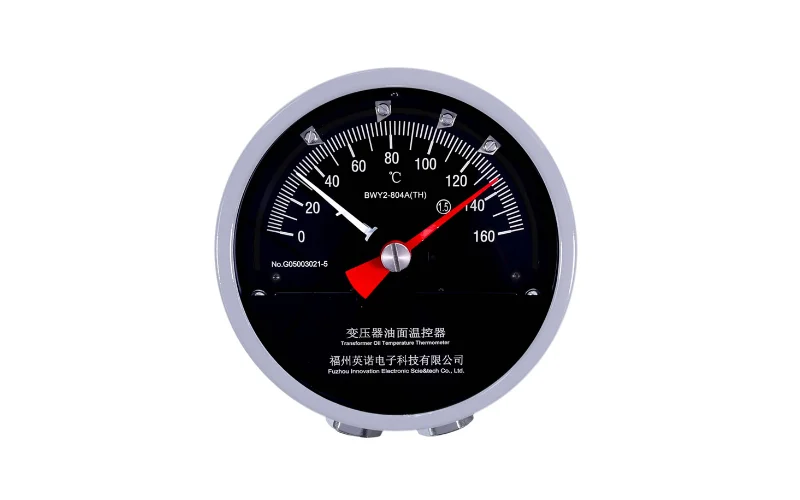
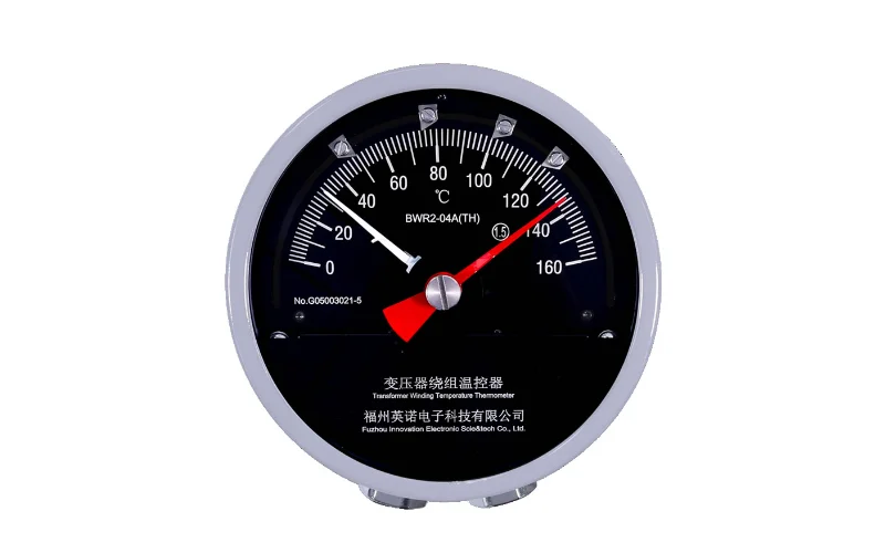
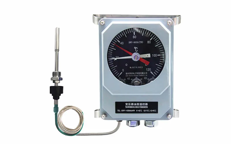
Winding temperature indicators estimate winding thermal condition using top-oil temperature and load-current-related heating. Adjustable contacts can be assigned to cooling control, alarm and trip functions according to transformer design.
Conventional winding temperature indicators provide local indication and switching functions, while direct sensing measures temperature at selected winding locations.
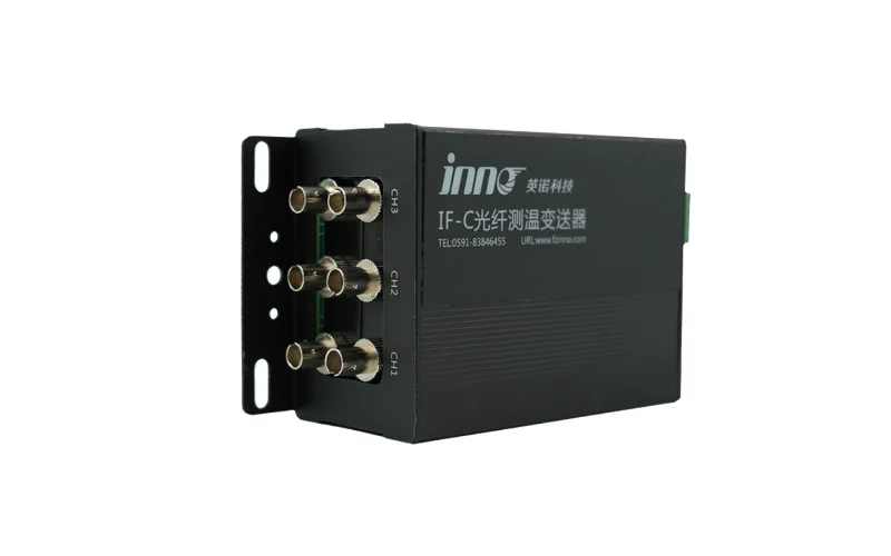
Direct winding hot-spot temperature measurement can use fiber optic probes where electrical isolation and immunity to electromagnetic interference are required. Probe location matters because hot-spot measurement targets the thermally critical part of the winding rather than general oil or tank temperature.
4.2 Top-Oil Temperature Monitoring
Top-oil temperature reflects transformer thermal condition at a different time scale from winding temperature. Oil temperature typically changes more slowly and is influenced by load, ambient temperature, cooling performance and internal losses.
Oil temperature indicators and electronic sensors can provide local display, switching contacts or remote signals depending on the selected device.
4.3 High-Temperature Warning and Cooling Response
High-temperature warning does not identify one specific root cause. Increased loading, fan or pump failure, high ambient temperature, blocked cooling paths, internal heating and sensor faults can all affect temperature readings.
Temperature alarms should therefore be evaluated with load current, cooling status, operating trend and related transformer condition data.
5. DGA Fault Gas Warnings and Trend Analysis
5.1 Dissolved Gas Alarm Logic
DGA monitoring identifies abnormal gas behavior in transformer oil. Alarm logic can use gas concentration, rate of change, combinations of gases or historical trends depending on system capability and project configuration.
Continuous online DGA monitoring provides additional visibility between laboratory oil tests, particularly for critical, ageing, heavily loaded or difficult-to-access transformers.
5.2 Gas Concentration, Rate of Change and Trends
| DGA Information | Por qué es importante |
|---|---|
| Gas Concentration | Shows the current measured level of individual or combined gases |
| Rate of Change | Highlights developing conditions before absolute values become high |
| Gas Combination | Supports assessment of thermal or electrical fault behavior |
| Loading Condition | Provides operating context for gas changes |
| Historical Trend | Allows comparison with the transformer's previous condition |
5.3 Interpreting Abnormal Gas Behavior
DGA alarms should not be treated as complete fault diagnoses. Gas type, concentration, rate of change, transformer loading, oil history and other diagnostic information all affect interpretation.
Rapid gas change under stable loading may deserve different attention from a slowly changing value observed over a long period. Trend context therefore matters as much as a single measured value.
6. Partial Discharge and Insulation Condition Alerts
6.1 Online Partial Discharge Detection
Partial discharge monitoring detects electrical discharge activity associated with insulation systems. Online monitoreo de descargas parciales en transformadores can use UHF, HFCT or ultrasonic sensing according to installation requirements and monitoring architecture.
6.2 PD Trends, Interference and Verification
Substation interference and external discharge sources can resemble transformer PD signals. Reliable assessment therefore requires trend analysis, signal characteristics and verification rather than a single isolated reading.
Configured PD alerts can help operators identify increasing discharge activity, but further diagnostic assessment may still be required before an internal insulation defect is confirmed.
6.3 Online Monitoring vs Offline Diagnostic Testing
Online PD monitoring follows discharge activity while the transformer remains in service. Offline diagnostic testing provides measurements under specific test conditions during factory testing, commissioning or planned outages.
Both methods serve different purposes. Continuous monitoring supports trend detection, while offline testing can provide controlled diagnostic measurements.
7. Oil, Bushing, OLTC and Cooling System Conditions
7.1 Oil Level and Pressure Abnormalities
Oil level and pressure provide additional information about transformer tank and oil-system condition. Leakage, abnormal volume changes, gas accumulation or pressure events can generate alarm or status signals.
Integrado oil temperature, level and pressure monitoring can combine several oil-system parameters for local indication or remote data acquisition.
7.2 Bushing Insulation Condition
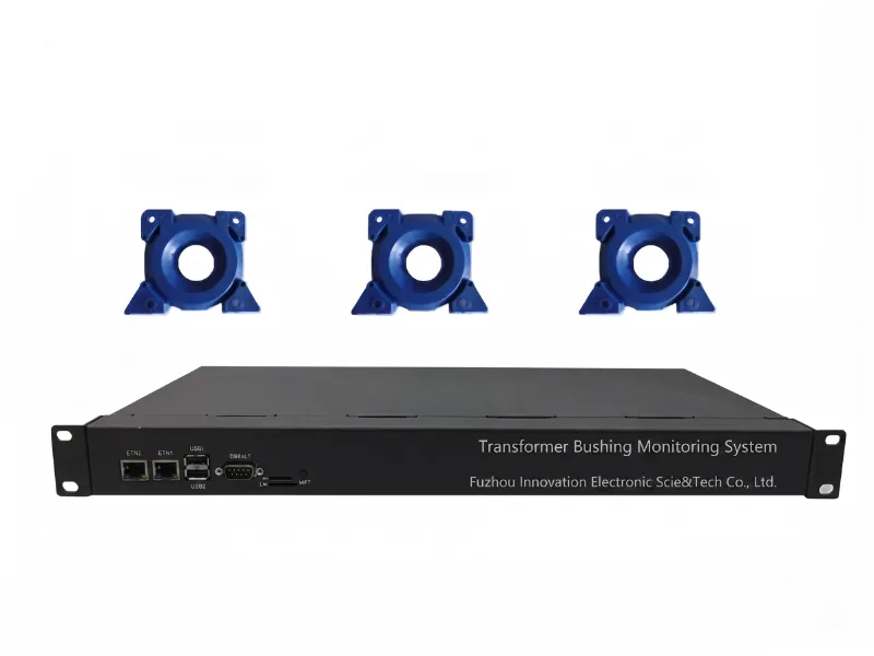
Transformer bushings can be monitored through capacitance, dielectric loss and leakage-current behavior. Changes from established baseline conditions may indicate insulation deterioration requiring further assessment.
Continuous bushing condition monitoring is particularly relevant on critical high-voltage transformers where bushing failure can have significant operational consequences.
7.3 OLTC Mechanical and Electrical Condition
On-load tap changers introduce mechanical and electrical components that operate repeatedly during transformer service. Motor current, vibration, temperature, torque and tap position can reveal changes in operating condition.
OLTC condition monitoring supports trend analysis of tap changer operation without relying only on scheduled inspection intervals.
7.4 Fan and Oil Pump Failure Indications
Cooling-system status helps explain temperature behavior. Fan failure, pump failure or abnormal cooling stage operation can reduce heat removal and cause winding or oil temperature to increase even when transformer loading remains unchanged.
8. Relay Outputs, Remote Monitoring and SCADA Integration
8.1 Signal Path from Sensor to Control Room
Monitoring signals can pass through local alarm contacts, serial communication, Ethernet networks or protocol gateways according to device capability and project architecture.
Sensor → Monitoring Device → Alarm Logic → Relay / Communication Output → Gateway / RTU / PLC → SCADA
Confiable transformer monitoring and SCADA integration also requires consistent register mapping, equipment tags, alarm priorities and communication-status supervision.
8.2 RS485, Ethernet, Relay and Analog Outputs
| Interface / Output | Typical Function | Common Application |
|---|---|---|
| Relay Contact | Discrete alarm or status output | Alarm panel, control cabinet or protection interface |
| RS485 / Modbus RTU | Transfers measured values, status and alarm information | PLC, RTU, gateway or SCADA |
| Ethernet | Network communication where supported | Monitoring server or substation network |
| 4–20 mA | Analog representation of measured values where available | Legacy controller or monitoring input |
| Protocol Gateway | Converts between field and control-center protocols | Multi-vendor monitoring systems |
| Pantalla local | Provides on-site values and status | Inspection, commissioning and local operation |
8.3 Remote Alarm and Monitoring Architecture
Remote monitoring becomes more useful when alarms include measured values and trends rather than only binary status. Operators can compare current values with previous behavior before deciding whether a condition requires inspection, testing or maintenance action.
9. Alarm Thresholds, Setpoints and Protection Coordination
9.1 Why Fixed Alarm Values Do Not Fit Every Transformer
No single temperature, gas, pressure or PD threshold applies to every transformer. Equipment design, rating, insulation system, cooling arrangement, sensor type and operating philosophy all influence suitable warning and trip levels.
9.2 Factors Affecting Alarm and Trip Setpoints
| Setting Factor | Por qué es importante |
|---|---|
| Manufacturer Recommendations | Reflect equipment-specific design and test information |
| Transformer Rating | Influences expected thermal and operating behavior |
| Sistema de aislamiento | Affects thermal limits and ageing characteristics |
| Cooling Mode | Changes temperature behavior and cooling-stage operation |
| Sensor Type and Location | Determines which physical quantity is being measured |
| Protection Coordination | Aligns monitoring alarms with protection logic |
| Historical Baseline | Helps separate abnormal change from normal variation |
| Operating Practice | Defines alarm priority, escalation and operator response |
9.3 Manufacturer Limits, Loading and Cooling Mode
Manufacturer documentation and site protection settings should remain the primary reference for alarm and trip configuration. Loading pattern and cooling mode also matter because expected temperature behavior changes between natural and forced cooling conditions.
Calculated winding temperature, direct hot-spot temperature and top-oil temperature are different quantities, so identical setpoints should not be assumed across different measurement methods.
10. Online Condition Monitoring and Early Fault Detection
10.1 Trend Analysis and Baseline Comparison
Online monitoring adds value by showing how transformer parameters change over time. Trend analysis can identify gradual deterioration, increasing rates of change and deviations from established operating baselines.
- Continuous measurement: captures behavior between routine inspections.
- Rate-of-change analysis: highlights rapidly developing conditions.
- Baseline comparison: compares current condition with previous normal operation.
- Remote visibility: provides data without requiring continuous on-site inspection.
10.2 Multi-Parameter Fault Detection
Temperature, DGA, PD, bushing and OLTC measurements provide different views of transformer health. Combining these indicators can improve assessment when abnormal conditions have more than one possible cause.
10.3 Remote Asset Health Monitoring
Transformer monitoring systems can provide local indication, alarm outputs and remote communication according to device configuration. Monitoring supports maintenance and operating decisions but does not replace protection relays, routine inspection or diagnostic testing.
11. Monitoring Devices and Alarm Output Options
11.1 Temperature, DGA and PD Monitoring Devices
Temperature, gas and insulation monitoring devices address different transformer risks. Equipment selection should follow the parameter that needs to be measured rather than using one device type for every application.
| Monitoring Option | Primary Function | Alarm / Output Capability | Comunicación |
|---|---|---|---|
| Indicador de temperatura del devanado BWR2 | Winding temperature indication and switching | Adjustable switch contacts | Pt100 or 4–20 mA depending on model |
| Sistema multicanal de monitoreo de temperatura por fibra óptica | Direct multi-point temperature measurement | Local display and configurable alarm output | RS485 / Modbus; optional outputs by configuration |
| Sistema de monitoreo de DGA en línea | Dissolved-gas measurement and trend analysis | Configurable alarm logic | RS485 and Ethernet-based communication depending on configuration |
| Sistema de monitoreo en línea de descargas parciales | Online PD detection and trend monitoring | Configurable PD alarm logic | RJ45 Ethernet and RS485 |
11.2 Bushing, OLTC and Oil Condition Monitoring
| Condition Area | Typical Parameters | Objetivo del monitoreo |
|---|---|---|
| Monitoreo de bujes | Capacitance, dielectric loss, leakage-current behavior | Identify changes in bushing insulation condition |
| Supervisión de OLTC | Motor current, vibration, temperature, torque, tap position | Track mechanical and electrical operating condition |
| Oil Condition Monitoring | Oil temperature, oil level and pressure | Monitor oil-system operating condition |
12. Selecting Monitoring by Transformer Risk
12.1 Matching Failure Modes to Monitoring Methods
Monitoring selection should begin with the transformer failure modes and operating risks that matter most for the asset.
| Primary Risk | Recommended Monitoring Approach | Main Condition Indicator |
|---|---|---|
| Sobrecalentamiento del bobinado | Monitoreo de la temperatura | Winding and oil temperature |
| Developing oil-filled transformer fault | Monitoreo de la DGA | Dissolved gases and gas trends |
| Insulation discharge | Monitoreo de descargas parciales | Electrical discharge activity |
| Deterioro de los bujes | Monitoreo de bujes | Electrical insulation parameters |
| Tap changer deterioration | Monitoreo del OLTC | Mechanical and electrical operating parameters |
| Multiple transformer risks | Multi-parameter monitoring | Combined thermal, chemical, electrical and mechanical condition |
12.2 Parameters to Confirm Before Equipment Selection
Transformer type, rating, insulation system, criticality, sensor access, required alarm outputs, communication protocol and SCADA architecture should be confirmed before monitoring equipment is selected.
Retrofit projects should also consider installation access, outage requirements and whether the intended measurement point can be reached safely without modifying transformer construction.
13. Transformer Alarm FAQ
13.1 What is a transformer alarm?
Transformer alarms are warning signals generated when monitored parameters, equipment status or sensor conditions meet configured criteria. Alarm signals normally require operator assessment and do not automatically isolate the transformer.
13.2 What causes transformer warning signals?
Abnormal signals can result from high temperature, unusual gas behavior, oil level or pressure changes, partial discharge, bushing deterioration, OLTC problems, cooling-system faults or sensor and communication failures.
13.3 What is the difference between alarm and trip?
Alarm functions notify operators that abnormal conditions require assessment. Trip signals are intended to initiate transformer isolation when connected to the protection trip circuit. Not every alarm condition leads to a trip.
13.4 What temperature should trigger a warning?
No single temperature applies to every transformer. Suitable thresholds depend on transformer design, rating, insulation system, cooling mode, sensor location, manufacturer recommendations and protection philosophy.
13.5 Can warning signals be sent to SCADA?
Monitoring devices can transmit status and alarm information through relay contacts, RS485, Ethernet or protocol gateways where supported. Available communication methods depend on the selected equipment and project architecture.
13.6 Can DGA systems provide automatic alerts?
Online DGA systems can generate alerts using gas concentration, rate of change or multi-gas trend logic. Gas alerts should be evaluated with transformer loading, oil history and other diagnostic information.
13.7 Can partial discharge monitoring generate alerts?
Online PD monitoring can generate alerts based on configured discharge activity, trends or signal patterns. Interference and external discharge sources should be considered before abnormal activity is attributed to an internal insulation defect.
13.8 How are alarm and trip setpoints selected?
Setpoints are selected using manufacturer recommendations, transformer rating, insulation system, cooling mode, sensor location, protection coordination, historical behavior and owner operating practices.
13.9 What should be checked after an abnormal signal appears?
Operators normally verify the signal, review related parameters, compare load and cooling status, check recent trends and follow manufacturer and site operating procedures before deciding the next action.
13.10 Does every transformer need continuous online monitoring?
Continuous monitoring is not required for every transformer. Criticality, loading, age, failure consequence, site access, operating history and maintenance strategy determine whether online monitoring provides sufficient operational value.