Lista de verificación para el monitoreo de transformadores de potencia: parámetros, sensores, alarmas y comunicación
Fecha de publicación:30 de septiembre de 2026, 10:12:19
A power transformer monitoring system is only as good as the decisions made when it is specified. If a key parameter is missing, a sensor is installed in the wrong place, alarms are set too loosely, or data never reaches the control room, the system gives a false sense of security. This checklist brings those decisions together in one place so that engineers, asset managers and project teams can review a monitoring scope before purchase, during design and at commissioning.
The checklist is organized into four parts: which parameters to monitor, which sensors to use, how to set alarms and trips, and how to communicate the data. It applies mainly to oil-immersed power transformers from about 10 MVA upward, but most items can be scaled down for distribution and industrial units. For a wider introduction to the topic, see our overview of soluciones de monitoreo de transformadores.
Índice
- Step 1: Define the Monitoring Scope
- Step 2: Parameter Checklist
- Step 3: Sensor Selection Checklist
- Step 4: Alarm and Trip Setting Checklist
- Step 5: Communication and Integration Checklist
- Step 6: Installation and Commissioning Checklist
- Step 7: Operation and Maintenance Checklist
- Common Mistakes to Avoid
- Preguntas frecuentes
Step 1: Define the Monitoring Scope
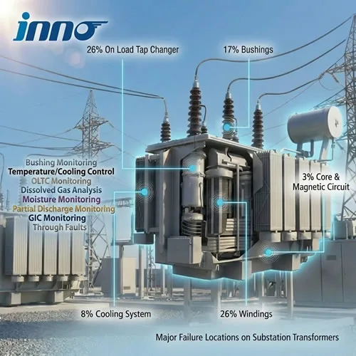
Before choosing any hardware, agree on why the transformer is being monitored and how much monitoring it justifies. A 500 MVA generator step-up unit and a 20 MVA industrial transformer need very different levels of investment.
| Checklist Item | Questions to Answer |
|---|---|
| ☐ Criticality | What happens if this transformer fails? Is there a spare or redundant unit? How long would replacement take? |
| ☐ Age and condition | Is it new, mid-life or near end of life? Are there known issues from past tests, DGA results or inspections? |
| ☐ Loading profile | Is it heavily loaded, cyclically loaded or expected to run overloads? Is it supplying variable renewable generation? |
| ☐ Site conditions | Is the site staffed or remote? What are the ambient temperature range, humidity, altitude and pollution level? |
| ☐ Existing equipment | Which gauges, relays and sensors are already installed? Can they be reused or integrated? |
| ☐ Objectives | Is the goal protection, dynamic loading, life extension, condition-based maintenance or all of these? |
A practical way to scale the scope is to group transformers into tiers. Basic monitoring covers temperatures, oil level and protective devices. Standard monitoring adds online DGA and cooling control. Comprehensive monitoring adds bushing, partial discharge and tap changer monitoring. Our guide to Métodos y estrategias de monitoreo del estado de los transformadores explains this tiered approach in more depth.
Step 2: Parameter Checklist
The table below lists the parameters most commonly monitored on power transformers, what each one reveals and a suggested priority. "Essential" items belong on almost every power transformer. "Recommended" items are justified on most critical units. "Optional" items depend on specific risks.
Thermal Parameters
| Parámetro | What It Reveals | Priority |
|---|---|---|
| ☐ Top-oil temperature | Overall thermal state, cooling performance | Essential |
| ☐ Winding hot-spot temperature | Insulation aging rate, overload capability | Essential |
| ☐ Ambient temperature | Reference for temperature rise and loading calculations | Essential |
| ☐ Bottom-oil temperature | Cooler efficiency, oil circulation | Recommended |
| ☐ Cooler inlet and outlet temperature | Blocked or failed radiators and heat exchangers | Opcional |
Temperature is the foundation of transformer monitoring because it directly governs insulation life. The difference between oil and winding measurements is explained in our article on oil temperature gauges versus winding temperature gauges, and the design limits behind them are covered in Límites y valores nominales del aumento de temperatura de los transformadores.
Electrical and Load Parameters
| Parámetro | What It Reveals | Priority |
|---|---|---|
| ☐ Load current (each phase) | Loading level, unbalance, input for thermal models | Essential |
| ☐ Voltage | Overexcitation risk, reference for bushing monitoring | Recommended |
| ☐ Harmonics | Additional losses and heating from nonlinear loads | Opcional |
| ☐ Core and clamp ground current | Multiple core grounding points, circulating currents | Recommended |
Insulation and Oil Condition Parameters
| Parámetro | What It Reveals | Priority |
|---|---|---|
| ☐ Dissolved gases (DGA) | Overheating, arcing, partial discharge, paper degradation | Essential for critical units |
| ☐ Moisture in oil | Wet insulation, seal failures, reduced dielectric strength | Recommended |
| ☐ Bushing capacitance and tan delta | Condenser layer breakdown, moisture in bushings | Recommended above about 110 kV |
| ☐ Partial discharge | Insulation defects, voids, surface tracking | Recommended for high-voltage or suspect units |
For insulation-related parameters, see our transformer insulation monitoring application page and our guide to partial discharge monitoring in transformers.
Mechanical and Auxiliary Parameters
| Parámetro | What It Reveals | Priority |
|---|---|---|
| ☐ Main tank and conservator oil level | Leaks, thermal expansion issues | Essential |
| ☐ Buchholz relay and sudden pressure relay status | Internal faults, gas accumulation | Essential |
| ☐ Pressure relief device status | Severe internal faults | Essential |
| ☐ Cooling fan and pump status | Cooling failures, motor faults | Essential for forced-cooled units |
| ☐ OLTC tap position, operation count and drive motor data | Contact wear, mechanism problems, excessive operations | Recommended where an OLTC is fitted |
| ☐ Breather condition | Saturated silica gel, moisture ingress into the conservator | Opcional |
| ☐ Vibration or acoustic signals | Loose windings or core, mechanical deformation | Opcional |
If you are still deciding which faults matter most for your fleet, our Guía sobre los modos de falla de los transformadores maps each failure mechanism to the parameters that detect it.
Step 3: Sensor Selection Checklist
Each parameter can usually be measured in more than one way. The right choice depends on accuracy needs, whether the transformer is new or already in service, and how the data will be used.
Temperature Sensors
| Tipo de sensor | Measures | Strengths | Limitations |
|---|---|---|---|
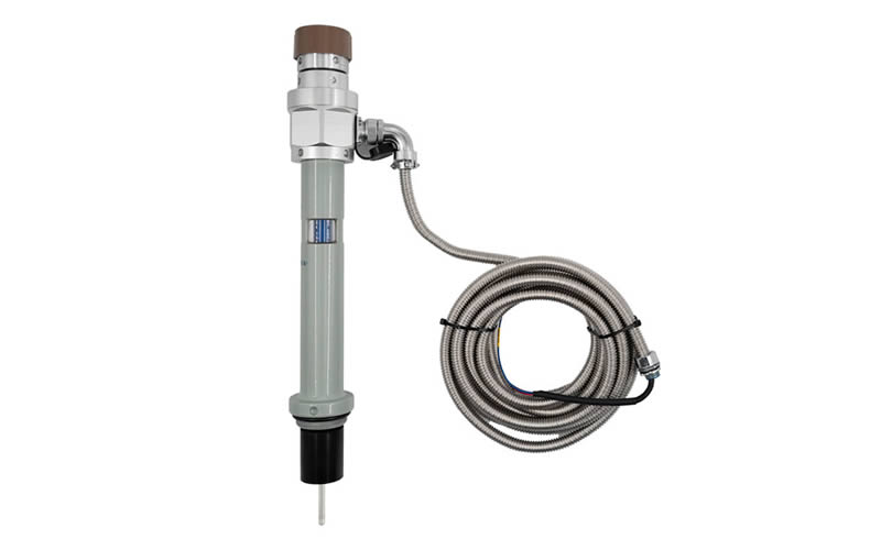
| Oil temperature indicator (dial thermometer with Pt100) | Temperatura máxima del aceite | Simple, proven, local display and contacts | Measures oil only, not windings |
| Winding temperature indicator (thermal image) | Calculated hot spot from oil temperature plus a CT-heated element | Low cost, retrofit-friendly | Simulated, not direct; accuracy depends on setup and the heat-run data |
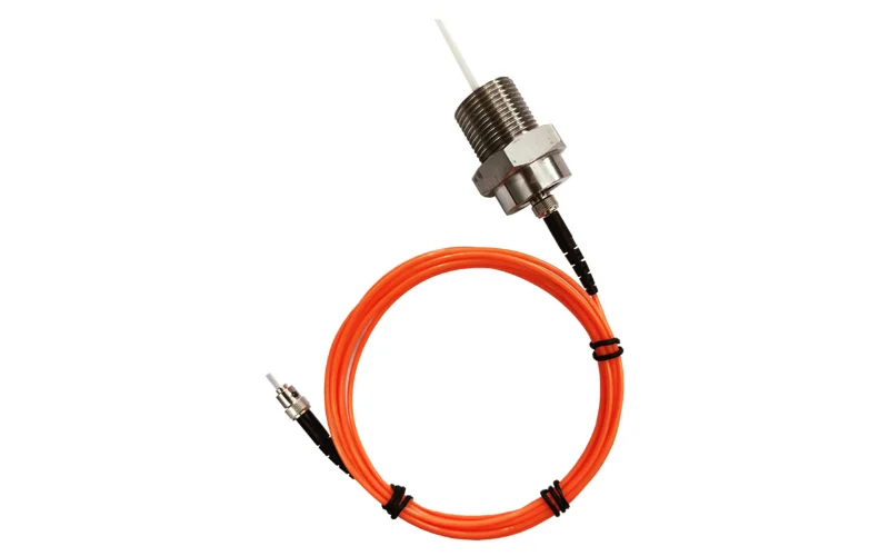
| Fluorescent fiber optic sensors | Direct winding hot-spot temperature | Direct measurement, immune to high voltage and EMI, fast response | Probes must be installed during manufacture or a major rebuild |
| Pt100 resistance sensors | Oil, ambient and cooler temperatures | Accurate, standard 3- or 4-wire signal | Cannot be placed on energized windings |
Checklist items:
- ☐ Specify direct hot-spot measurement for new critical transformers. Fiber optic sensors are the only practical way to measure winding hot spots directly. Options include the sensor de fibra óptica para el monitoreo de puntos calientes en bobinas, the polyimide fiber optic sensor for windings y el armored fiber optic sensor for oil-immersed windings.
- ☐ Agree the number and position of probes with the transformer manufacturer. Probe locations should be based on the heat-run test or thermal design calculations, typically at the top of the HV and LV windings where the hot spot is expected.
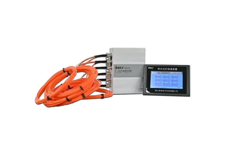
- ☐ Check the number of channels needed. Large transformers often use 6 to 12 probes. A multi-channel fiber optic temperature monitoring system or a 6-channel demodulator can serve one transformer from a single unit.
- ☐ Plan the tank wall feedthrough and the external extension cable route to the monitoring cabinet.
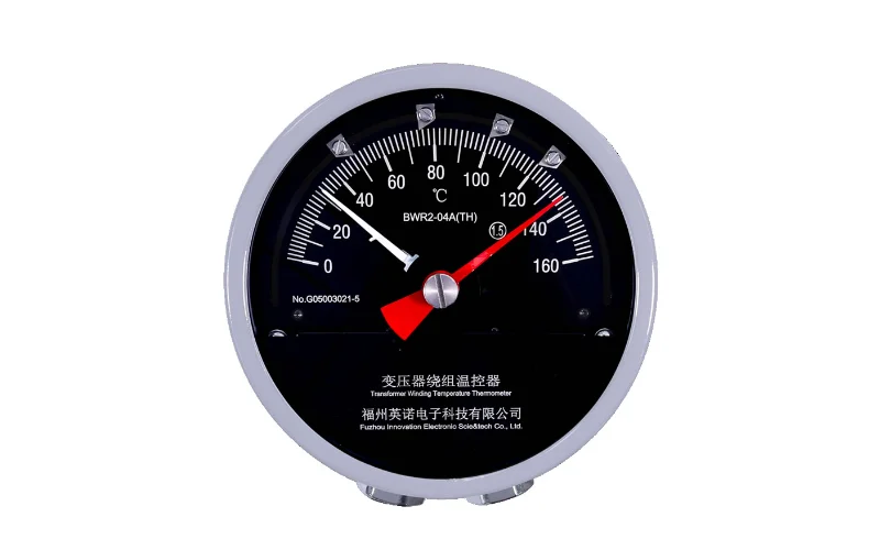
- ☐ Keep conventional indicators as a backup. Standard devices such as the BWY-802/803A oil temperature indicator y el BWR-04/06AJTH winding temperature indicator provide local display and independent alarm contacts.
For a detailed comparison of hot-spot measurement methods, see Medición de la temperatura en los puntos calientes de los devanados de los transformadores y sensores y nuestro fiber optic temperature measurement system for oil-immersed transformers.
Oil, Insulation and Auxiliary Sensors
- ☐ DGA monitor type. Choose between single-gas (usually hydrogen or a composite), multi-gas or full-spectrum monitors. Critical transformers normally justify a multi-gas unit that can support diagnostic methods such as the Duval Triangle. See our sistema de monitoreo de DGA en línea and the article comparing online DGA with oil sampling.
- ☐ Moisture sensor. Check whether moisture is included in the DGA monitor or needs a separate probe. Record oil temperature at the same point for meaningful interpretation.
- ☐ Bushing sensors. Confirm test tap types and use adapters with built-in protection. The transformer bushing monitoring system measures capacitance, tan delta and leakage current online.
- ☐ Partial discharge sensors. Decide between UHF sensors on drain valves or dielectric windows, HFCT sensors on ground leads and bushing tap coupling. See our sistema de monitoreo en línea de descargas parciales en transformadores.
- ☐ OLTC sensors. Include motor current or power, tap position, and diverter switch oil temperature. See the Sistema de monitoreo en línea OLTC para transformadores.
- ☐ Oil level and pressure. Use transmitters with analog or digital outputs instead of contacts only, so trends can be recorded. See our sistema de monitoreo de la temperatura, el nivel y la presión del aceite de los transformadores.
- ☐ Current and voltage signals. Confirm that CT and VT secondary signals are available for the monitoring system, with suitable burden and isolation.
Step 4: Alarm and Trip Setting Checklist
Alarm settings should always follow the transformer manufacturer's recommendations and the owner's loading policy. The values below are typical starting points drawn from common practice and the loading guides IEC 60076-7 and IEEE C57.91. They are not a substitute for design-specific limits.
Temperature Alarms
| Parámetro | Typical Stage 1 (Cooling or Alarm) | Typical Stage 2 (High Alarm) | Typical Trip |
|---|---|---|---|
| Temperatura máxima del aceite | About 75 °C to 85 °C | About 85 °C to 95 °C | About 95 °C to 105 °C |
| Winding hot spot | About 95 °C to 105 °C | About 110 °C to 120 °C | About 130 °C to 140 °C |
| Cooling stage start | Fans and pumps are commonly staged on winding or top-oil temperature, for example first stage at about 65 °C to 75 °C and second stage about 10 K higher | ||
For reference, IEC 60076-7 gives a hot-spot limit of 120 °C for normal cyclic loading and 140 °C for long-time emergency loading on non-thermally upgraded paper, with a top-oil limit of 105 °C. Actual settings are usually lower to leave a margin.
Condition Monitoring Alarms
| Parámetro | Alarm Basis | Reference |
|---|---|---|
| Gases disueltos | Absolute concentration levels plus rate of increase per gas | IEEE C57.104, IEC 60599 |
| Moisture in oil | Absolute ppm and relative saturation, adjusted for temperature and voltage class | IEC 60422, manufacturer limits |
| Bushing C1 and tan delta | Change from baseline, for example a few percent for C1 or a doubling of tan delta | IEEE C57.152, manufacturer limits |
| Descarga parcial | Magnitude, repetition rate and trend, with noise rejection | IEC 60270, site baseline |
| Core ground current | Commonly around 100 mA in many utility practices, adjusted to the design | Owner practice, manufacturer limits |
Alarm Design Checklist
- ☐ Use at least two alarm stages (warning and high alarm) before any trip.
- ☐ Add rate-of-change alarms for DGA, bushing and temperature trends. Fast changes are often more important than absolute values.
- ☐ Set hysteresis and time delays to prevent alarm chattering during normal load cycles.
- ☐ Decide which alarms are hardwired to protection and which are advisory only. Trips should rely on proven, independent devices.
- ☐ Assign an owner and a response procedure to every alarm, including who is notified and within what time.
- ☐ Allow a learning period after commissioning to establish baselines for condition parameters before tightening thresholds.
- ☐ Review alarm settings after major events such as through-faults, overloads, oil processing or repairs.
Understanding what drives temperature alarms helps set them sensibly. Our Guía sobre el sobrecalentamiento de los transformadores covers the common causes and early symptoms.
Step 5: Communication and Integration Checklist
Monitoring data has value only when it reaches the people and systems that act on it. Communication should be specified as carefully as sensors.
| Interface | Uso típico | Notes |
|---|---|---|
| Dry contacts (relay outputs) | Alarms, trips, cooling control | Simple and robust; essential for protection functions |
| 4–20 mA analog outputs | Temperatures and levels to RTUs or PLCs | Widely supported, one value per signal pair |
| Modbus RTU (RS-485) / Modbus TCP | Data exchange with local controllers and SCADA | Simple and common; check register maps early |
| IEC 61850 | Digital substations, integration with protection IEDs | Supports standardized logical nodes for transformer monitoring; request the ICD/CID files |
| DNP3 / IEC 60870-5-104 | Telecontrol links to utility control centers | Common in North America and Europe respectively |
Integration Checklist
- ☐ Confirm the protocol used by the substation automation system and the control center.
- ☐ Obtain point lists, register maps or IEC 61850 configuration files before the factory acceptance test.
- ☐ Synchronize time across all monitoring devices, for example via SNTP or IEEE 1588 PTP, so events can be correlated.
- ☐ Decide where data is stored, how long it is kept and who can access it.
- ☐ Apply cybersecurity measures such as network segmentation, role-based access, secure remote access and patch management, following standards such as IEC 62351 and IEC 62443.
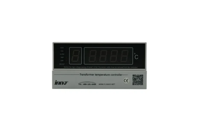
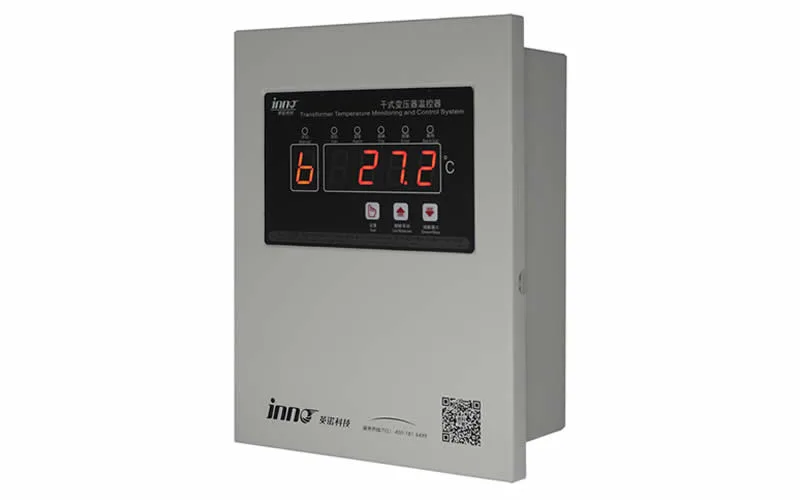
- ☐ Provide a local display in the substation for operators, such as a host de visualización de temperatura por fibra óptica o LCD display instrument, so key values remain visible if communication is lost.
- ☐ Combine data from temperature, DGA, bushing, PD and OLTC monitors on one platform so correlations are easy to see. See our monitoreo de transformadores de potencia application page for integrated architectures.
Step 6: Installation and Commissioning Checklist
- ☐ Verify every sensor against the drawings, including channel numbers and probe identities.
- ☐ Check fiber optic probe continuity and signal strength before and after tank filling.
- ☐ Confirm sensor readings are plausible: all oil temperatures close to ambient on a de-energized transformer, and oil level consistent with the conservator gauge.
- ☐ Record baseline offline test results for bushings, DGA and moisture before energization.
- ☐ Test every alarm and trip contact end to end, from the sensor to the control room display.
- ☐ Test cooling control logic, including fan and pump staging and failover.
- ☐ Verify communication with SCADA, including point mapping, scaling, quality flags and time stamps.
- ☐ Document all settings, firmware versions and network configurations.
- ☐ Train operators and maintenance staff on the displays, alarms and response procedures.
Step 7: Operation and Maintenance Checklist
| Frequency | Tasks |
|---|---|
| Daily or continuous | ☐ Review active alarms ☐ Check communication status ☐ Watch for sudden trend changes |
| Monthly | ☐ Review temperature and load trends ☐ Review DGA trends ☐ Check cooling system operation |
| Annually | ☐ Compare online DGA with laboratory samples ☐ Calibrate or verify indicators and transmitters ☐ Test alarm and trip contacts ☐ Check for firmware and security updates |
| At planned outages | ☐ Offline bushing and insulation tests to validate online data ☐ Inspect sensor cabling and tank feedthroughs ☐ Replace consumables such as DGA monitor filters or carrier gas |
| After events | ☐ Review data after through-faults, overloads or protection operations ☐ Reassess alarm settings if the transformer's condition has changed |
Common Mistakes to Avoid
- Relying only on calculated winding temperature. Thermal image indicators are useful, but they can differ noticeably from the true hot spot, especially during rapid load changes or with modified cooling.
- Missing the fiber optic opportunity. Direct hot-spot sensors must be installed during manufacture or major repair. If they are not specified at purchase, the chance is lost for decades.
- Buying data without a response plan. Alarms without an owner, procedure and escalation path are often ignored.
- Setting alarms without baselines. Condition parameters such as DGA, PD and bushing values vary between units. Fixed generic thresholds lead to either false alarms or missed faults.
- Leaving communication until the end. Protocol mismatches and missing register maps are among the most common causes of commissioning delays.
- Monitoring parameters in isolation. A single rising value can be ambiguous. Correlating temperature, load, DGA and bushing data gives far more confident diagnoses.
Preguntas frecuentes
What is the minimum monitoring every power transformer should have?
At a minimum: top-oil temperature, winding temperature (calculated or direct), oil level, Buchholz and pressure relief devices, and cooling system status. Critical transformers should also have online DGA and direct winding hot-spot measurement.
Is direct fiber optic hot-spot measurement worth the cost?
For large or heavily loaded transformers, usually yes. Direct measurement allows safe dynamic loading, verifies thermal design and detects cooling problems quickly. The sensor cost is small compared with the value of the transformer and the extra loading capacity it can safely unlock.
Which communication protocol should I choose?
Use whatever the substation automation system and control center already support. IEC 61850 is preferred for new digital substations, while Modbus remains common for local integration. Most monitoring systems offer several protocols, so confirm compatibility early.
Can monitoring be added to an existing transformer?
Yes. Online DGA, bushing monitoring, PD sensors, OLTC monitoring, oil level and pressure transmitters, and upgraded temperature indicators can all be retrofitted. Direct winding hot-spot sensors are the main exception, since they normally require the active part to be accessed.
How often should alarm settings be reviewed?
Review them after commissioning once baselines are established, then at least annually and after any major event, repair or change in loading policy.
Plan Your Transformer Monitoring Project with Our Engineers
Whether you are specifying monitoring for a new transformer or upgrading an existing fleet, our team can help you define parameters, select sensors, set alarm strategies and integrate data with your control systems. We support projects for empresas de servicios públicos de la red eléctrica, generación de energía, energía renovable y subestaciones, así como substation transformer monitoring y monitoreo de la temperatura del transformador aplicaciones.
Browse our full range of solutions, review our certificaciones, o bien ponte en contacto con nuestro equipo to discuss your monitoring checklist.