Dissolved Gas Analysis in Transformers: Key Gases, Fault Types & DGA Interpretation
Date: 2026年9月29日 09:32:52
- Dissolved gas analysis (DGA) measures the fault gases dissolved in transformer insulating oil and is one of the most sensitive early-warning tools for oil-immersed transformers.
- Key gases include hydrogen (H2), methane (CH4), ethane (C2H6), ethylene (C2H4), acetylene (C2H2), carbon monoxide (CO) and carbon dioxide (CO2).
- Each gas points to a different fault type: hydrogen to partial discharge, ethylene to oil overheating, acetylene to arcing, and CO/CO2 to cellulose insulation stress.
- Recognised DGA interpretation methods include the key gas method, IEC 60599 gas ratios, the Duval Triangle and Total Dissolved Combustible Gas (TDCG).
- The rate of gas generation matters as much as absolute concentrations, so trending is essential.
- Online DGA monitoring closes the gap between routine lab samples and gives continuous visibility of fast-developing faults.
- DGA works best when combined with winding temperature, partial discharge, bushing and OLTC monitoring.
Table of Contents
- 1. What Is Dissolved Gas Analysis (DGA) in Transformers?
- 2. How Fault Gases Form in Transformer Insulating Oil
- 3. Key Gases in Transformer Oil and What Each One Indicates
- 4. DGA Fault Types: Partial Discharge, Arcing and Thermal Faults
- 5. DGA Interpretation Methods: Key Gas, Gas Ratios, Duval Triangle and TDCG
- 6. Oil Sampling, Laboratory DGA and Online DGA Monitoring
- 7. Online DGA Monitoring System: Typical Technical Parameters
- 8. Combining DGA with Temperature, Partial Discharge, Bushing and OLTC Monitoring
- 9. DGA Trending, Alarm Limits and Recommended Maintenance Actions
- 10. Common DGA Interpretation Mistakes to Avoid
- 11. Frequently Asked Questions (FAQ)
1. What Is Dissolved Gas Analysis (DGA) in Transformers? Transformer Oil Analysis Basics
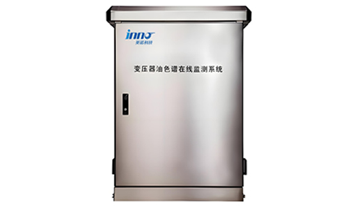
1.1 Dissolved gas analysis is a diagnostic technique that extracts the gases dissolved in transformer insulating oil and measures their concentrations. Because every type of internal fault produces a characteristic gas pattern, the results let engineers identify a developing problem long before it causes an outage.
1.2 Utilities, industrial plants and service providers use DGA as a core element of transformer condition assessment. The method is described in IEC 60599 and IEEE C57.104, while sampling and gas extraction practices are covered by IEC 60567 and the ASTM D3612 and D3613 methods.
1.3 Why DGA Matters for Oil-Immersed Transformer Reliability
Mineral oil and cellulose paper are the primary insulation materials in a power transformer. When thermal or electrical stress breaks down these materials, gases are released into the oil. Detecting them early supports planned maintenance, reduces unplanned failures and helps operators judge remaining insulation life. For a wider view of how DGA fits with other diagnostics, see this guide to transformer condition monitoring methods and parameters.
2. How Fault Gases Form in Transformer Insulating Oil and Cellulose Insulation
2.1 Fault gases form when energy in the transformer is high enough to break chemical bonds in the oil or paper. The type and amount of gas depend on the temperature or energy level at the fault location.
2.2 Oil Decomposition Gases
At low temperatures, oil breaks down mainly into hydrogen and methane. As temperature increases, ethane and ethylene appear. At very high temperatures and in electrical arcs, acetylene is produced.
2.3 Paper Decomposition Gases
2.3.1 Carbon Oxides as Indicators of Solid Insulation Stress
Overheated cellulose releases carbon monoxide and carbon dioxide, together with furanic compounds. These gases are also produced by normal ageing, so their meaning depends on trend, ratio and context.
2.4 Normal Ageing versus Fault Conditions
A healthy transformer always contains some dissolved gas. Interpretation focuses on abnormal levels, unusual gas combinations and increasing generation rates. Persistent overloading and localised heating are common triggers, as discussed in this article on transformer overheating causes, symptoms and prevention.
3. Key Gases in Transformer Oil: Hydrogen, Methane, Ethylene, Acetylene and Carbon Monoxide
3.1 The table below summarises the main gases analysed in DGA and the faults they usually indicate.
| Gas | Formula | Typical Source | Main Fault Association |
|---|---|---|---|
| Hydrogen | H2 | Oil breakdown at low energy | Partial discharge, corona, general overheating |
| Methane | CH4 | Oil breakdown | Low-temperature thermal faults, partial discharge |
| Ethane | C2H6 | Oil breakdown | Thermal faults at moderate temperature |
| Ethylene | C2H4 | Oil breakdown at high temperature | Medium and high-temperature thermal faults |
| Acetylene | C2H2 | Very high temperature or arcing | Arcing, high-energy discharge, severe overheating |
| Carbon monoxide | CO | Cellulose decomposition | Paper overheating and ageing |
| Carbon dioxide | CO2 | Cellulose decomposition | Paper overheating and ageing |
| Oxygen / Nitrogen | O2 / N2 | Atmosphere or oil preservation system | Sealing condition, oxidation, ingress |
3.2 Combustible Gases versus Non-Fault Gases
Hydrogen, hydrocarbons and carbon monoxide are combustible fault gases and are summed in the TDCG value. Oxygen and nitrogen are atmospheric gases; their ratio helps assess the oil preservation system and possible leaks.
3.3 Why Acetylene Deserves Immediate Attention
Acetylene forms only under extreme conditions. Even small, increasing amounts should trigger a follow-up sample and a review of the loading and operating history, because they may indicate arcing.
4. DGA Fault Types: Partial Discharge, Low-Energy and High-Energy Arcing, and Thermal Faults
4.1 IEC 60599 classifies internal faults into a small set of categories. Recognising the category is the first step towards a maintenance decision.
| Code | Fault Type | Typical Dominant Gases | Common Causes |
|---|---|---|---|
| PD | Partial discharge | H2, CH4 | Voids, gas bubbles, poor impregnation, insulation defects |
| D1 | Low-energy discharge | H2, C2H2 | Sparking, tracking, floating potentials |
| D2 | High-energy discharge | H2, C2H2, C2H4 | Arcing, flashover, short circuits between windings |
| T1 | Thermal fault below 300 °C | CH4, C2H6 | Overloading, restricted oil flow |
| T2 | Thermal fault 300–700 °C | C2H4, CH4 | Circulating currents, poor contacts, core heating |
| T3 | Thermal fault above 700 °C | C2H4, H2, some C2H2 | Severe overheating, large circulating currents |
4.2 Partial Discharge Faults
Partial discharge produces mostly hydrogen with some methane. It can progress to more serious insulation damage if left unmanaged. Dedicated sensors add precision; see this overview of partial discharge monitoring in transformers.
4.3 Discharge of Energy: Arcing
4.3.1 Low-Energy versus High-Energy Discharges
Low-energy discharges create hydrogen and acetylene at modest rates. High-energy arcing adds significant ethylene and generates gas quickly, which is why rapid, repeated sampling or continuous monitoring is valuable.
4.4 Thermal Faults
4.4.1 Hot Spots in Windings, Core and Connections
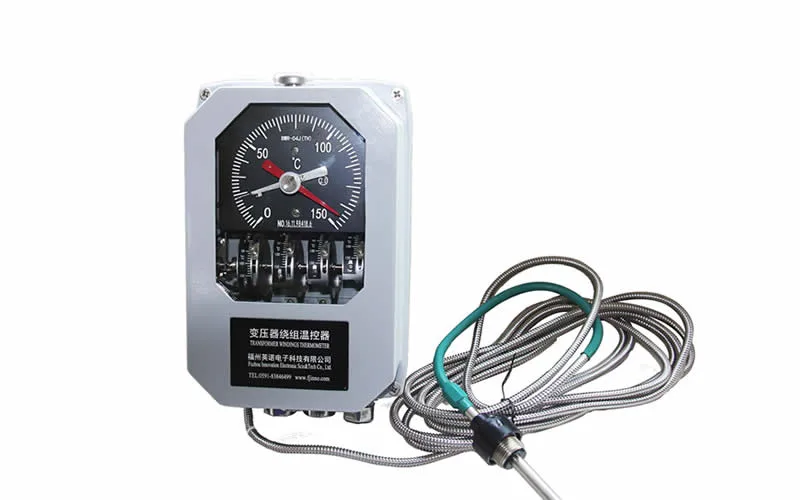
Thermal faults are identified by rising methane, ethane and ethylene. Direct winding temperature measurement provides independent evidence; read more about transformer winding hot spot temperature measurement and fiber optic temperature measurement in transformers.
5. DGA Interpretation Methods: Key Gas Method, IEC 60599 Gas Ratios, Duval Triangle and TDCG
5.1 No single method is perfect. Experienced engineers compare two or more approaches and always review the trend history.
5.2 Key Gas Method
The key gas method links the predominant gas to a fault type. For example, ethylene dominance suggests oil overheating, hydrogen dominance suggests partial discharge, acetylene with hydrogen suggests arcing, and carbon monoxide dominance suggests cellulose involvement.
5.3 IEC 60599 Gas Ratio Method
Three ratios are calculated: C2H2/C2H4, CH4/H2 and C2H4/C2H6. The table shows the classic ratio ranges used to classify fault types (NS = non-significant).
| Fault | C2H2 / C2H4 | CH4 / H2 | C2H4 / C2H6 |
|---|---|---|---|
| PD | NS | < 0.2 | < 0.2 |
| D1 | > 1 | 0.1 – 0.5 | > 1 |
| D2 | 0.6 – 2.5 | 0.1 – 1 | > 2 |
| T1 | NS | > 1 but NS | < 1 |
| T2 | < 0.1 | > 1 | 1 – 4 |
| T3 | < 0.2 | > 1 | > 4 |
5.4 Duval Triangle
5.4.1 Graphical Fault Classification
The Duval Triangle plots the relative percentages of methane, ethylene and acetylene on a triangular chart, with zones for PD, D1, D2, T1, T2, T3 and a mixed thermal/electrical zone (DT). Its visual format makes it popular for quick classification and reporting.
5.5 TDCG and Gas Generation Rates
5.5.1 Why Rate of Change Is More Informative
TDCG offers an overall severity indicator, but a stable high value can be less concerning than a smaller value that is climbing quickly. Guidance in IEEE C57.104 uses both concentration levels and generation rates when recommending sampling intervals.
5.6 CO2/CO Ratio for Paper Involvement
A low CO2/CO ratio (commonly below 3) can suggest that a fault involves paper insulation, whereas a high ratio (above about 10) is often associated with normal ageing. Treat it as supporting evidence rather than a stand-alone verdict.
6. Oil Sampling, Laboratory DGA versus Online DGA Monitoring
6.1 Laboratory DGA remains the reference method. Oil is drawn into a syringe or bottle, sent to a laboratory and analysed by gas chromatography. Correct sampling technique, sample labelling and prompt shipping directly affect result quality.
6.2 Limitations of Periodic Sampling
Interval sampling can miss fast-developing faults. Sample handling errors, transport delays and laboratory variation also add uncertainty. Many operators therefore add continuous monitoring on critical units. This comparison of online DGA vs oil sampling explains the trade-offs in detail.
6.3 Benefits of Online DGA Monitoring
6.3.1 Continuous Data, Faster Response
An online dissolved gas analysis (DGA) monitoring system for transformer oil extracts gas from the oil on the transformer and measures it automatically at set intervals. Operators see trends in near real time and can set alarms on both concentration and rate of change. For a broader look at the technology, visit transformer online DGA monitoring or the dissolved gas analysis solution page.
7. Online DGA Monitoring System: Typical Technical Parameters for Transformer Gas Sensors
7.1 The table below lists typical specification ranges found in online DGA monitors used on oil-immersed power transformers. Always confirm exact values against the current product datasheet before specifying equipment.
| Parameter | Typical Specification |
|---|---|
| Monitored gases | H2, CO, CH4, C2H4, C2H6, C2H2 (some models add CO2, O2, moisture in oil) |
| Gas detection principle | Gas chromatography, photoacoustic spectroscopy or sensor-based detection |
| Oil-gas separation | Membrane or headspace extraction |
| Sampling interval | Configurable, from hourly to daily |
| Communication | RS485 (Modbus), Ethernet, IEC 61850 or DNP3 (model dependent) |
| Power supply | AC 220 V or DC 110/220 V |
| Operating temperature | −40 °C to +55 °C (outdoor installation) |
| Ingress protection | IP55 or higher enclosure |
| Installation | Oil valve connection on the transformer main tank, with oil return |
| Outputs | Alarm relays, trend data, remote software access |
7.2 Selection Criteria
Match the number of gases to the risk level of the transformer. Large step-up and grid transformers usually justify multi-gas monitors, while distribution units may only need hydrogen-based screening. Check the communication protocol with your SCADA system and confirm the oil valve type before ordering.
8. Combining DGA with Winding Temperature, Partial Discharge, Bushing and OLTC Monitoring
8.1 DGA shows that a fault is present, but other measurements help locate it and confirm its cause. A layered approach reduces false alarms and improves decision quality.
8.2 Temperature Monitoring
If DGA points to thermal faults, direct winding temperature data can confirm hot-spot conditions. Explore transformer oil temperature, level and pressure monitoring and the fiber optic temperature monitoring solution.
8.3 Partial Discharge and Bushing Monitoring
Hydrogen-rich results are often cross-checked with a transformer partial discharge online monitoring system. Bushing faults are a leading cause of catastrophic transformer failures, so a transformer bushing monitoring system is a useful complement.
8.4 OLTC Monitoring
The on-load tap changer is a frequent source of arcing-related gases. A transformer OLTC online monitoring system helps distinguish tap changer activity from main tank faults.
8.5 Application and System Level
See how these tools fit together in oil-immersed transformer monitoring, transformer insulation monitoring and the complete transformer monitoring solution. For failure patterns and detection methods, read the transformer failure modes guide.
9. DGA Trending, Alarm Limits and Recommended Maintenance Actions
9.1 Trending is the backbone of good DGA practice. Record every result with the date, load, oil temperature and any switching or fault events so that changes can be explained.
9.2 Setting Alarm Thresholds
Use IEEE C57.104 or IEC 60599 typical values as a starting point, then adapt them to the age, design and history of each transformer. Set both an absolute alarm and a rate-of-rise alarm.
9.3 Recommended Actions after an Abnormal Result
9.3.1 Step-by-Step Response
- Resample promptly to confirm the result and rule out sampling error.
- Increase sampling frequency while the gas rate is elevated.
- Classify the fault using at least two interpretation methods.
- Review loading, cooling, tap changer operation and recent through-faults.
- Schedule electrical tests or an internal inspection when the evidence supports it.
- Reduce load or remove the transformer from service if acetylene is rising quickly.
10. Common DGA Interpretation Mistakes and Best Practices for Transformer Diagnostics
10.1 Even experienced teams make avoidable errors. The list below covers the most frequent ones.
10.2 Typical Mistakes
- Relying on one sample instead of a trend.
- Ignoring sampling contamination, such as air bubbles or dirty syringes.
- Applying ratio tables when gas levels are too low to be meaningful.
- Overlooking gases carried over from a previous fault, oil treatment or tap changer leakage.
- Failing to record when oil was degassed or filtered.
10.3 Best Practices
Follow standard sampling procedures, use accredited laboratories, keep a full event log and pair DGA with electrical and temperature measurements. If you need help selecting a monitoring solution, visit contact us, review our certificates or learn more about us.
11. Frequently Asked Questions (FAQ) about Dissolved Gas Analysis in Power Transformers
1. What is dissolved gas analysis in a transformer?
It is a test that measures gases dissolved in insulating oil to detect internal faults such as overheating, partial discharge and arcing at an early stage.
2. Which gases are measured in a DGA test?
Standard tests measure hydrogen, methane, ethane, ethylene, acetylene, carbon monoxide and carbon dioxide, along with oxygen and nitrogen.
3. What does high hydrogen mean in transformer oil?
High hydrogen commonly indicates partial discharge or low-energy electrical activity, but it can also come from overheating. Check the trend and the other gases before drawing conclusions.
4. What does acetylene in transformer oil indicate?
Acetylene points to arcing or very high temperatures. Any confirmed increase deserves a prompt investigation.
5. How often should transformer oil be tested for DGA?
Many utilities test annually for normal units and more often for critical, older or abnormal transformers. Follow the sampling intervals recommended in IEEE C57.104 or your company policy.
6. What is the Duval Triangle?
It is a graphical method that plots methane, ethylene and acetylene percentages to classify faults into PD, discharge and thermal zones.
7. What is the difference between online DGA and laboratory DGA?
Laboratory DGA analyses a physical sample taken at intervals, while online DGA measures gases continuously or at frequent intervals directly on the transformer. Many operators use both, with the laboratory serving as a cross-check.
8. What is TDCG in DGA?
Total Dissolved Combustible Gas is the sum of the combustible fault gases: hydrogen, methane, ethane, ethylene, acetylene and carbon monoxide. It is used as an overall indicator of gas activity.
9. Can DGA detect all transformer faults?
No. DGA is highly sensitive to thermal and electrical faults in the oil-paper system but may not reveal mechanical problems such as winding deformation. Complementary tests are recommended.
10. What standards govern DGA interpretation?
IEC 60599 and IEEE C57.104 cover interpretation, IEC 60567 covers sampling and gas extraction, and ASTM D3612 and D3613 describe analysis and sampling methods.