

Temperatura dos pontos quentes nos enrolamentos de transformadores: medição, monitoramento e sensores
发布时间:6 de setembro de 2026, 12:04:22
- Transformer winding hot spot temperature is the highest local temperature within a current-carrying winding and its surrounding insulation, rather than the average temperature of the complete winding.
- Hot spot temperature can be calculated using transformer thermal models or measured directly at selected locations using embedded temperature sensors.
- A conventional winding temperature indicator (WTI) generally provides an indirect thermal indication, while an embedded sensor measures temperature at its actual physical location.
- Fiber optic winding temperature sensors are particularly useful for direct measurements inside high-voltage transformers because the sensing point can remain electrically passive and immune to electromagnetic interference.
- Reliable monitoramento de pontos quentes em transformadores depends on sensor placement, winding geometry, loading, oil flow, cooling conditions and the selected monitoring method—not only on sensor accuracy.
Monitoring transformer winding hot spot temperature is an important part of transformer thermal management and condition assessment. Top-oil temperature, average winding temperature and the actual winding hot spot describe different thermal conditions, so they should not be treated as interchangeable measurements.
For modern monitoramento de transformadores, engineers may combine calculated thermal models, conventional winding temperature indicators and direct embedded sensors. This guide explains how these methods differ, where winding hot spots develop, how sensors should be positioned, and when direct transformer winding hot spot monitoring provides additional information.
Table of Contents
- 1. What Is Transformer Winding Hot Spot Temperature?
- 2. Why Transformer Hot Spot Temperature Matters
- 3. Where Does Transformer Winding Hot Spot Temperature Occur?
- 4. How Is Transformer Hot Spot Temperature Measured?
- 5. Transformer Hot Spot Calculation and Thermal Models
- 6. Direct Transformer Winding Temperature Measurement
- 7. Transformer Winding Temperature Sensors Compared
- 8. Fiber Optic Sensors for Transformer Hot Spot Monitoring
- 9. Sensor Placement for Transformer Winding Hot Spots
- 10. Transformer Hot Spot Monitoring System Architecture
- 11. Transformer Hot Spot Temperature, Loading and Insulation Aging
- 12. Engineering Examples for Transformer Hot Spot Monitoring
- 13. Common Transformer Hot Spot Monitoring Mistakes
- 14. How to Select a Transformer Hot Spot Monitoring Method
- 15. Frequently Asked Questions
- 16. Conclusion
1. What Is Transformer Winding Hot Spot Temperature?
1.1 Transformer Winding Hot Spot Temperature Definition
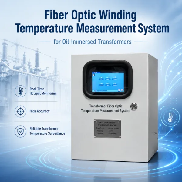
Transformer winding hot spot temperature describes a localized region of the winding where conductor and insulation temperature is higher than surrounding areas. It is a local thermal condition, not simply another name for transformer oil temperature or average winding temperature.
A winding contains many conductors, insulation layers, spacers and cooling passages. Current losses generate heat throughout the winding, but the heat is not always distributed evenly. Variations in conductor losses, oil circulation, winding geometry and local cooling can create regions with higher temperature.
Because the hot spot is local, a temperature measurement is meaningful only when its physical location is understood. A sensor installed 50 mm away from the actual hottest conductor may record a different temperature even though both measurements are inside the same winding.
1.2 Hot Spot Temperature vs Average Winding Temperature
Average winding temperature represents the winding as a whole, while temperatura do ponto quente do transformador concerns the highest local thermal region. Average values are useful for transformer testing and thermal assessment, but localized heating may exceed the average.
This distinction is one reason direct fiber optic temperature sensors for transformer winding hot spot monitoring are used in applications where engineers want temperature information from specific internal winding locations.
1.3 Transformer Hot Spot Temperature vs Top Oil Temperature
Top-oil temperature measures the thermal condition of transformer oil near the upper part of the tank. It is an important operating parameter, but it should not be interpreted as the actual winding hot spot.
| Temperature Parameter | O que isso representa | Typical Measurement Method | Direct Winding Hot Spot? |
|---|---|---|---|
| Temperatura ambiente | Environment surrounding the transformer | Ambient sensor | No |
| Temperatura máxima do óleo | Oil temperature near the upper tank region | Oil temperature indicator / sensor | No |
| Average Winding Temperature | Average thermal condition of the winding | Calculation, resistance method or indirect indication | No |
| Temperatura do ponto crítico do enrolamento | Local high-temperature region in the winding | Thermal calculation or embedded local sensor | Yes, when measured at the selected hot-spot location |
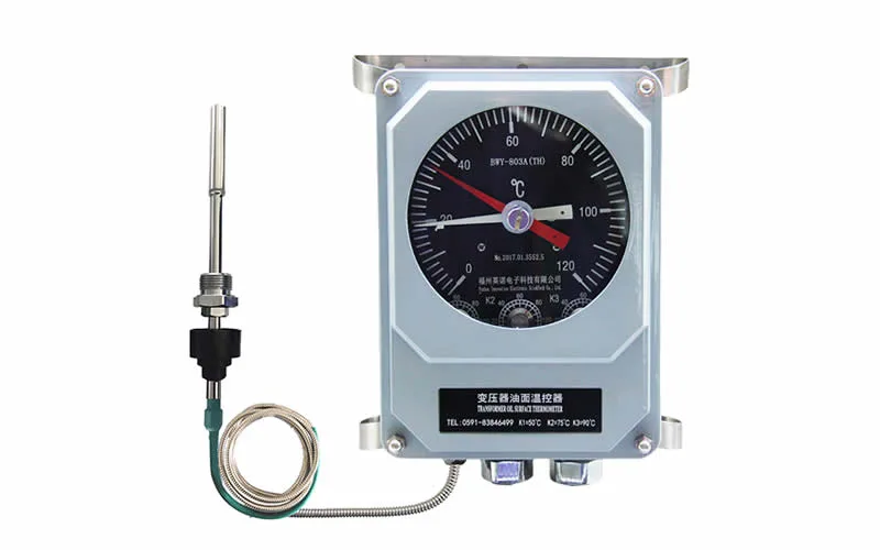
For conventional oil temperature indication, products such as a indicador de temperatura do óleo do transformador serve a different purpose from embedded winding temperature sensing.
2. Why Transformer Hot Spot Temperature Matters
2.1 Transformer Hot Spot Temperature and Insulation Aging
Transformer insulation is exposed to electrical, mechanical and thermal stresses throughout its service life. Local winding temperature is therefore relevant to thermal aging assessment, particularly in oil-immersed transformers using cellulose-based solid insulation.
IEC 60076-7 addresses transformer operation from the perspective of operating temperature and thermal aging, while IEEE C57.91 provides loading guidance that includes transformer temperature criteria, loading conditions, cooling effects and loss-of-life considerations.
For an engineer, the practical point is straightforward: two transformers carrying similar loads may not develop identical internal temperatures if their winding designs, cooling conditions, ambient environments or operating histories differ.
2.2 Hot Spot Temperature During Transformer Overloading
When transformer load increases, conductor losses and winding heating also change. The winding, oil and cooling system have different thermal time responses, so the temperature inside the winding does not necessarily follow the same profile as top-oil temperature.
This becomes particularly important during temporary overloads, rapid load changes or cooling-system transitions. A transformer temperature monitoring system can combine multiple temperature inputs rather than relying on a single tank-level measurement.
2.3 Hot Spot Temperature in Transformer Condition Monitoring
Temperature should also be considered alongside other transformer condition indicators. Thermal stress is only one potential contributor to transformer degradation.
Depending on transformer criticality, a broader monitoring strategy may incorporate online dissolved gas analysis, transformer partial discharge monitoring, bushing monitoring, and OLTC monitoring.
Hot spot temperature therefore works best as part of a broader transformer health picture rather than as an isolated diagnostic value.
3. Where Does Transformer Winding Hot Spot Temperature Occur?
3.1 Transformer Winding Geometry and Local Hot Spots
The winding hot spot cannot be assumed to occur at the same geometric location in every transformer. Its position depends on the actual electromagnetic and thermal design.
Important influences include:
- HV and LV winding geometry
- Conductor dimensions and current density
- Axial and radial cooling ducts
- Oil-flow distribution
- Local eddy and stray losses
- Insulation thickness and thermal resistance
- Winding clamping and mechanical structures
- Transformer cooling mode
3.2 Axial and Radial Temperature Distribution
Temperature changes can occur both axially and radially through a winding. A region near the upper part of a winding may be warmer under certain cooling conditions, but assuming that the highest axial position is always the true hot spot can lead to poor sensor placement.
Likewise, inner and outer winding regions may have different losses and oil-flow conditions. The expected hot spot should therefore be determined from transformer-specific thermal design information whenever possible.
3.3 Cooling Ducts and Oil Flow
Oil flow is a major part of thermal behavior in an oil-immersed transformer. Local restrictions, uneven flow distribution or changes in cooling operation can alter winding temperature distribution.
This is one reason a direct winding sensor should not be treated as independent of transformer design. The quality of transformer hot spot measurement depends on both sensor performance and whether the probe is actually positioned near a thermally significant region.
4. How Is Transformer Hot Spot Temperature Measured?
There are two broad engineering approaches to obtaining transformer winding hot spot temperature information: calculated temperature e direct local temperature measurement.
4.1 Indirect Transformer Hot Spot Measurement
Indirect methods infer winding thermal behavior from parameters such as transformer loading, oil temperature and thermal characteristics. Conventional winding temperature indicators and software thermal models are widely used because they do not require a sensor to be physically embedded in the winding hot-spot region.
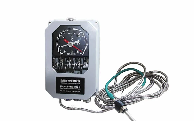
A transformer winding temperature indicator, for example, serves a different measurement role from an embedded fiber optic probe.
4.2 Direct Transformer Winding Temperature Measurement
Direct winding temperature measurement uses a sensor installed at a selected physical location inside or close to the winding. The measured value represents the temperature at that location at that moment.
For high-voltage windings, conventional electrically conductive sensing approaches can create insulation and electromagnetic design challenges. This has led to the use of electrically passive fiber optic temperature sensors for transformer windings.
4.3 Calculated vs Direct Transformer Hot Spot Temperature
| Fator | Calculated Hot Spot | Direct Local Measurement |
|---|---|---|
| Measurement Basis | Thermal model and operating inputs | Physical temperature sensor |
| Actual Sensor Inside Winding | Not required | Required for embedded measurement |
| Temperature Location | Estimated model location | Actual sensor location |
| Retrofit Potential | Generally easier | Embedded winding installation may require manufacturing or major refurbishment access |
| Design Dependency | Depends on model parameters | Depends strongly on correct sensor placement |
| Main Value | Continuous thermal estimation | Direct observation of selected internal locations |
Neither method should automatically be considered superior. In critical applications, calculated and direct temperatures can be used together to provide complementary information.
5. Transformer Hot Spot Calculation and Thermal Models
5.1 Inputs Used for Transformer Hot Spot Calculation
A transformer thermal model may consider several operating variables rather than a single measured temperature. Typical inputs or model parameters can include:
- Load current or load factor
- Temperatura ambiente
- Top-oil temperature
- Winding-to-oil temperature gradient
- Cooling mode and cooling-system state
- Thermal time constants
- Transformer-specific design parameters
These variables help estimate internal temperatures that cannot otherwise be accessed in an operating transformer.
5.2 IEC 60076-7 and Transformer Thermal Loading
IEC 60076-7:2018 provides loading guidance for mineral-oil-immersed power transformers and addresses operation under different ambient temperatures and load conditions, operating temperatures, thermal aging and thermal models.
The standard is therefore relevant when assessing the relationship between transformer loading and thermal behavior. However, an online monitoring article should not treat a standard calculation as a substitute for transformer-specific engineering data.
5.3 IEEE C57.91 and Transformer Hot Spot Temperature
IEEE C57.91-2025 is the current IEEE loading guide for mineral-oil-immersed transformers and step-voltage regulators. It includes techniques for assessing loading effects, temperature criteria, cooling effects and sample temperature calculations.
For monitoring-system design, these standards provide a framework. Actual alarm limits and loading decisions should still follow transformer manufacturer requirements, insulation system design and the applicable project specification.
5.4 Limitations of Transformer Hot Spot Calculation
Thermal calculations depend on model assumptions. Real transformers can experience changes in cooling efficiency, ambient conditions, local oil flow, manufacturing tolerances and loading patterns.
A calculated hot spot should therefore be understood as an engineering estimate. Direct winding temperature measurement can provide an independent temperature observation at selected points, but it also has its own limitation: the sensor only measures where it is physically installed.
6. Direct Transformer Winding Temperature Measurement
6.1 Embedded Transformer Winding Temperature Sensors
An embedded temperature probe is normally planned around the expected winding hot-spot region. This planning should occur before winding assembly when the sensor must be physically integrated within the winding insulation structure.
For new transformer manufacturing, this provides an opportunity to coordinate the sensor location with thermal calculations and winding drawings before final assembly.
6.2 Why Sensor Position Matters
A crucial engineering principle is:
A temperature sensor measures its own physical location; it does not automatically identify the absolute hottest point in the transformer.
For example, suppose a three-phase transformer uses 12 embedded temperature probes. If the probes are distributed across selected axial and radial regions, the monitoring system obtains 12 direct temperature observations. It does not prove that no uninstrumented location is warmer.
This is why sensor placement should be supported by transformer thermal design, historical experience or temperature-rise test information whenever possible.
6.3 Direct Measurement and Thermal Model Validation
Direct measurements can also be compared with calculated values. If the thermal model predicts one winding temperature trend while embedded probes repeatedly show a different trend under comparable loads, engineers have additional information for investigating assumptions, sensor positions or cooling behavior.
This combined approach can provide more useful information than treating calculated and measured temperatures as competing technologies.
7. Transformer Winding Temperature Sensors Compared
7.1 Winding Temperature Indicator for Transformers
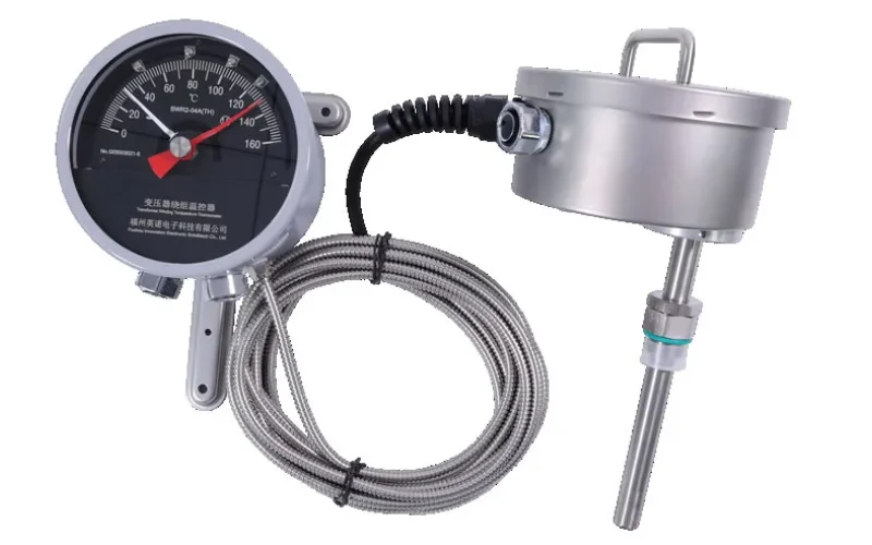
A winding temperature indicator is a conventional solution for transformer temperature indication and control. Depending on the design, it can provide local indication and outputs for alarms or cooling control.
INNO provides transformer WTI options such as the BWR-04/06AJTH transformer winding temperature indicator e BWR2 winding temperature indicator.
7.2 RTD Temperature Sensors
RTDs measure temperature through the predictable change in electrical resistance of the sensing element. They are widely used in industrial temperature measurement, but their metallic sensing and wiring require appropriate electrical and insulation consideration in high-voltage environments.
7.3 Thermocouples
Thermocouples generate a thermoelectric voltage related to temperature difference. Their simple construction and broad industrial use make them practical for many applications, but they remain electrically conductive sensors.
7.4 Fiber Optic Winding Temperature Sensors
A fiber optic winding temperature sensor transmits the measurement optically rather than relying on a metallic electrical signal at the sensing point. This is particularly useful inside transformer windings where electrical isolation and immunity to electromagnetic fields are important.
| Method | Direct Local Measurement | Electrical Signal at Sensing Point | EMI Consideration | Typical Transformer Role |
|---|---|---|---|---|
| Modelo térmico | No | No sensor required at hot spot | Not applicable to model itself | Calculated hot-spot estimation |
| WTI | Typically indirect | Depends on design | System design dependent | Winding temperature indication / control |
| RTD | Yes at installed location | Yes | Requires consideration | General transformer temperature measurement |
| Thermocouple | Yes at installed location | Yes | Requires consideration | Industrial temperature measurement |
| Fiber Optic Sensor | Yes at installed location | No metallic measurement signal required at sensing point | Highly suitable for EMI-intensive environments | Embedded winding hot-spot monitoring |
8. Fiber Optic Sensors for Transformer Hot Spot Monitoring
8.1 Why Use Fiber Optic Sensors Inside Transformer Windings?
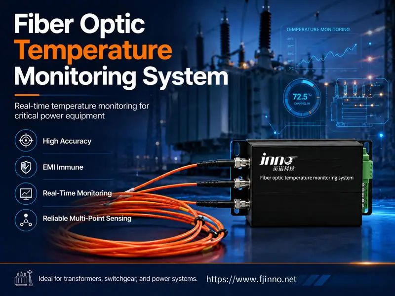
Fiber optic sensing is particularly useful where an electrical temperature sensor would be difficult to integrate safely. The optical probe can be designed as an electrically passive sensing element, while the optoelectronic interrogator remains outside the high-voltage winding region.
Typical reasons for using a fiber optic temperature monitoring system include:
- Strong electromagnetic fields
- High electrical potential differences
- Medição direta em pontos selecionados do enrolamento
- Need for small embedded sensing probes
- Multi-point transformer temperature monitoring
- Integration with remote monitoring systems
8.2 Fluorescence Fiber Optic Temperature Sensing
Fluorescence-based fiber optic sensing is a point temperature measurement technology. A fluorescent material at the probe tip is optically excited, and the monitoring instrument evaluates the temperature-dependent fluorescence response.
This approach should not be confused with distributed temperature sensing. For transformer winding hot spots, the goal is usually to obtain temperature from selected critical locations rather than to measure a continuous temperature profile along kilometers of fiber.
8.3 Fiber Optic Probe Options for Transformer Windings
Different transformer mechanical environments may require different probe constructions. For embedded winding installations, a polyimide fiber optic temperature sensor can be selected where a compact winding-compatible probe construction is needed.
For applications requiring additional mechanical protection, an armored fiber optic temperature sensor for oil-immersed transformer windings provides another product configuration.
The correct choice should consider winding structure, routing space, mechanical stress, oil compatibility and installation procedure rather than selecting only by temperature range.
9. Sensor Placement for Transformer Winding Hot Spots
9.1 Use Thermal Design Before Installing Winding Temperature Sensors
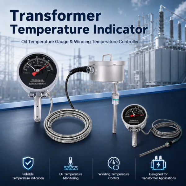
Probe placement should ideally begin with predicted thermal distribution rather than arbitrary spacing. Transformer designers can identify likely high-temperature regions using winding calculations, electromagnetic loss analysis, oil-flow analysis and previous test data.
A practical sequence is:
- Identify thermally critical windings.
- Estimate likely axial and radial hot-spot zones.
- Select several representative measurement points.
- Review mechanical and insulation constraints.
- Route optical fibers without interfering with winding assembly.
- Verify all channels before final transformer closure.
9.2 How Many Fiber Optic Sensors Does a Transformer Need?
There is no universal sensor quantity that fits every transformer. Probe count depends on transformer rating, phases, winding arrangement, monitoring objective and required redundancy.
For example, consider an illustrative three-phase transformer monitoring configuration with two windings of interest per phase. Engineers might select two temperature locations on each monitored winding, producing:
3 phases × 2 monitored windings × 2 sensing locations = 12 measurement points.
This is an engineering example only, not a universal requirement. Another transformer might require fewer points, while a large or thermally complex design could justify substantially more.
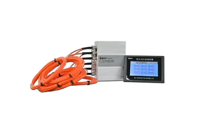
For applications requiring many measurement points, a multi-channel fiber optic temperature measurement and monitoring system can centralize the temperature channels.
9.3 Practical Fiber Optic Probe Installation Checklist
- Confirm expected hot-spot location before winding completion.
- Check that the sensing tip is positioned at the intended thermal location.
- Avoid excessive fiber bending or crushing.
- Protect fiber leads during winding compression and assembly.
- Maintain compatibility with transformer insulation structures.
- Clearly identify each probe and monitoring channel.
- Check optical continuity before inaccessible assembly stages.
- Verify the complete measurement chain before final commissioning.
10. Transformer Hot Spot Monitoring System Architecture
A complete transformer winding temperature monitoring system normally contains more than the embedded sensor.
Embedded Fiber Optic Probe → Optical Fiber → Temperature Interrogator → Temperature Data → Alarm / Logic → PLC or SCADA
10.1 Embedded Fiber Optic Temperature Probe
The probe provides the local sensing point. Its mechanical construction and positioning must match the winding application.
10.2 Fiber Optic Temperature Interrogator
The interrogator provides optical excitation, detects the returned optical response and converts it into temperature data. Systems can be configured for different channel counts depending on the number of winding locations being monitored.
Where fewer measurement points are required, a 3-channel fiber optic temperature transmitter for power transformer winding monitoring may be appropriate. Larger installations can use multi-channel platforms.
10.3 Local Display and Monitoring Interface
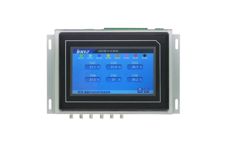
Applications requiring local display can use a fiber optic temperature display integrated host or a system configuration with local temperature visualization.
10.4 PLC and SCADA Integration
Transformer winding temperature data can be integrated into a broader plant or substation monitoring architecture. Depending on the selected product configuration, industrial systems may provide interfaces such as RS485, Modbus, analog signals or relay outputs.
Exact communication interfaces should always be confirmed against the selected model rather than assumed for every fiber optic monitoring device.
11. Transformer Hot Spot Temperature, Loading and Insulation Aging
11.1 Loading Changes Transformer Winding Temperature
Transformer winding temperature is dynamic. When load changes, conductor losses change, but winding, oil and cooling-system temperatures respond with different thermal time constants.
This means a transformer experiencing a short high-load period may show a different relationship between winding temperature and top-oil temperature than it does under long-term steady-state loading.
11.2 Cooling System Operation and Transformer Hot Spots
Cooling condition is also important. Changes in natural or forced cooling affect the rate at which heat is removed from the winding and oil.
A thermal monitoring strategy should therefore consider not only measured temperature but also cooling-system status, load and ambient condition. This broader approach is especially valuable for monitoramento de transformadores de potência.
11.3 Transformer Hot Spot Temperature and Thermal Aging
Both IEC and IEEE loading guidance connect operating temperature with transformer insulation life assessment. Higher thermal stress can accelerate insulation aging, but the relationship depends on insulation system, moisture, oxygen, operating history and other conditions.
For this reason, fixed rules such as “every temperature increase of X degrees always halves transformer life” should not be applied without considering the standard, insulation system and assumptions behind the calculation.
12. Engineering Examples for Transformer Hot Spot Monitoring
12.1 Illustrative 12-Point Transformer Winding Monitoring Configuration
Consider a new three-phase oil-immersed power transformer where the design team wants direct temperature information from both HV and LV windings.
| Transformer Arrangement | Three-phase |
|---|---|
| Monitored Windings | HV and LV |
| Sensing Points per Winding | 2 illustrative locations |
| Total Measurement Points | 12 |
| Measurement Type | Direct embedded point temperature sensing |
| Objetivo do monitoramento | Compare critical winding temperatures across phases and winding positions |
The 12-point arrangement is not a standard requirement. It demonstrates how channel count can be derived from the monitoring objective.
If thermal modeling indicates additional critical zones, the system may use more channels. INNO also provides higher-channel-count configurations such as a 64-channel fluorescent fiber optic temperature measurement system for applications requiring substantially more sensing points.
12.2 Example: Comparing Direct and Calculated Temperature
Suppose a monitoring system records temperatures at 12 embedded locations while the transformer monitoring software simultaneously calculates winding hot-spot temperature from load and oil-temperature data.
Instead of expecting both values to be numerically identical, engineers should compare:
- Temperature trend during load increases
- Temperature trend during cooling transitions
- Phase-to-phase differences
- Difference between HV and LV windings
- Measured-versus-calculated trend over repeated operating cycles
A persistent change in this relationship can be more informative than looking at a single temperature snapshot.
12.3 Example: Combining Winding and Oil Temperature Monitoring
Direct winding temperature does not eliminate the value of oil monitoring. A complete thermal picture can combine embedded winding sensors with an oil temperature, level and pressure monitoring system.
This allows the operator to distinguish between local winding heating and broader changes in transformer oil or tank conditions.
13. Common Transformer Hot Spot Monitoring Mistakes
13.1 Treating Top Oil Temperature as Winding Hot Spot Temperature
Top oil and winding hot spot describe different parts of the transformer thermal system. One should not simply substitute for the other.
13.2 Assuming One Sensor Always Measures the Hottest Location
A single embedded sensor gives one direct measurement point. If the actual hot spot shifts because of loading or cooling conditions, another winding location may become warmer.
13.3 Installing Sensors Without Thermal Design Input
Adding more sensors does not automatically improve monitoring quality if they are positioned in thermally unimportant areas. Probe quantity and probe location should be considered together.
13.4 Ignoring Fiber Routing and Mechanical Protection
The fiber lead must survive transformer winding assembly and long-term service. Excessive bending, crushing, poor lead-out routing or mechanical damage can compromise the measurement channel even when the temperature sensing principle itself is correct.
13.5 Comparing Calculated and Direct Temperatures Without Considering Location
A calculated hot-spot temperature represents a modeled thermal quantity. A direct sensor represents a physical location. A numerical difference between them is not automatically evidence that one measurement is wrong.
13.6 Using Unverified Alarm Thresholds
Alarm and trip settings should be based on transformer design, insulation system, manufacturer recommendations, operating strategy and applicable standards. A generic alarm value copied from another transformer should not be treated as universally applicable.
14. How to Select a Transformer Hot Spot Monitoring Method
14.1 Use Calculated Transformer Hot Spot Monitoring When
- Embedded winding access is unavailable.
- The transformer is already in service.
- Load and thermal-model inputs are available.
- The monitoring objective is continuous thermal estimation.
14.2 Use a Winding Temperature Indicator When
- A conventional transformer temperature indication method is required.
- Local indication, alarm or cooling control is part of the design.
- Direct embedded winding measurement is not necessary.
14.3 Use Direct Fiber Optic Winding Temperature Measurement When
- The transformer is new or accessible during major refurbishment.
- Direct winding temperature information is required.
- Measurement points are located in high-voltage or strong electromagnetic environments.
- Thermal-model validation is valuable.
- Multiple winding hot-spot locations need to be observed directly.
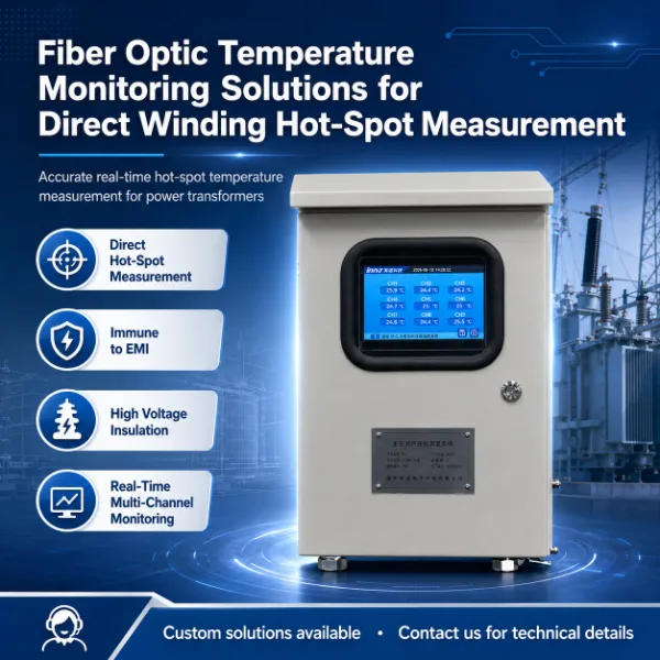
For these applications, a dedicated fiber optic temperature measurement system for oil-immersed transformers can combine embedded probes and external monitoring electronics.
14.4 Use Combined Transformer Thermal Monitoring When
For critical transformers, direct and indirect monitoring can complement each other.
A combined approach may include:
- Top-oil temperature
- Calculated winding hot spot
- Direct embedded winding temperature
- Load data
- Cooling-system status
- Oil level and pressure
- DGA or partial discharge data where required
This architecture provides more context than any individual measurement channel.
15. Frequently Asked Questions About Transformer Winding Hot Spot Temperature
15.1 What is transformer winding hot spot temperature?
Transformer winding hot spot temperature is the highest local temperature within the winding and associated insulation region. It differs from average winding temperature and top-oil temperature because it represents a localized thermal condition.
15.2 What is the difference between top oil temperature and winding hot spot temperature?
Top-oil temperature represents transformer oil near the upper tank region. Winding hot-spot temperature represents a local high-temperature region within a winding. The winding hot spot can therefore be significantly different from the oil temperature measured elsewhere in the transformer.
15.3 How is transformer hot spot temperature calculated?
Transformer hot spot calculations typically use operating and thermal parameters such as load, ambient or oil temperature, winding gradients, cooling conditions and thermal time constants. IEC 60076-7 and IEEE C57.91 provide recognized loading and thermal guidance for applicable transformer types.
15.4 Does a winding temperature indicator directly measure the transformer hot spot?
A conventional WTI generally provides an indirect winding temperature indication rather than placing a physical sensor at the actual internal winding hot spot. Its role should therefore be distinguished from direct embedded sensor measurement.
15.5 Can fiber optic sensors directly measure transformer winding temperature?
Yes. An embedded fiber optic probe can directly measure temperature at the physical location where the sensing tip is installed. This is why fiber optic winding hot-spot sensors are used for selected internal measurement points.
15.6 Are fiber optic temperature sensors affected by transformer electromagnetic fields?
Fiber optic sensing transmits optical rather than conventional electrical measurement signals at the sensing point, making it highly suitable for environments with strong electromagnetic fields. The complete system still requires correct engineering and installation outside the sensing region.
15.7 How many fiber optic temperature sensors should be installed in a transformer?
There is no universal number. Sensor quantity depends on transformer design, phases, winding arrangement, predicted hot spots, channel redundancy and monitoring objectives. A three-phase transformer may use several sensors per winding, but the final layout should be based on the specific thermal design.
15.8 Where should transformer winding temperature sensors be installed?
They should be installed near predicted thermally critical winding locations. Thermal calculations, winding geometry, cooling-path design and previous temperature-rise experience can all help determine suitable positions.
15.9 Can embedded winding temperature sensors be retrofitted into an existing transformer?
Installing a sensor directly inside an existing winding is usually much more difficult than planning the sensor during transformer manufacturing. Major refurbishment may provide access in some projects, but retrofit feasibility depends on transformer construction and the required measurement location.
15.10 What is the best method for transformer hot spot monitoring?
There is no single method that is best for every transformer. Thermal calculation is valuable for continuous estimation, WTI provides conventional winding temperature indication, and embedded fiber optic sensors provide direct measurements at selected internal locations. Critical transformers can benefit from combining these methods.
16. Conclusion: Transformer Winding Hot Spot Temperature Monitoring
Transformer winding hot spot temperature is a local thermal quantity that should be distinguished from average winding temperature and top-oil temperature. Engineers can estimate it through transformer thermal models or directly measure selected winding locations using embedded temperature sensors.
Calculated monitoring is practical and valuable for continuous thermal assessment, while direct transformer winding temperature measurement provides physical temperature data from the installed sensing points. Neither approach eliminates the importance of correct transformer thermal design.
For high-voltage and strong electromagnetic environments, electrically passive fiber optic probes provide a practical method of obtaining direct winding temperature data. Their effectiveness, however, depends heavily on correct hot-spot prediction, sensor placement, fiber routing and system integration.
For a complete solution, explore INNO's transformer temperature monitoring solutions, fiber optic temperature monitoring systems e transformer winding hot spot monitoring applications.
Related Transformer Monitoring Resources
- Soluções de monitoramento de transformadores
- Monitoramento de transformadores de potência
- Monitoramento de transformadores imersos em óleo
- Sensor de temperatura de fibra óptica para monitoramento de pontos quentes nos enrolamentos de transformadores
- Sensor de temperatura de fibra óptica de poliimida para enrolamentos de transformadores
- Sistema multicanal de medição e monitoramento de temperatura por fibra óptica







