
What Is a Fiber Optic Temperature Sensor Probe?
A fiber optic temperature sensor is a point-type thermal measurement device that uses fluorescent optical principles to detect temperature at the exact location where the probe tip is placed. Unlike conventional thermocouples or RTDs that rely on electrical signals, these probes transmit data entirely through light — making them the only practical solution for direct winding temperature measurement inside high-voltage power transformers.
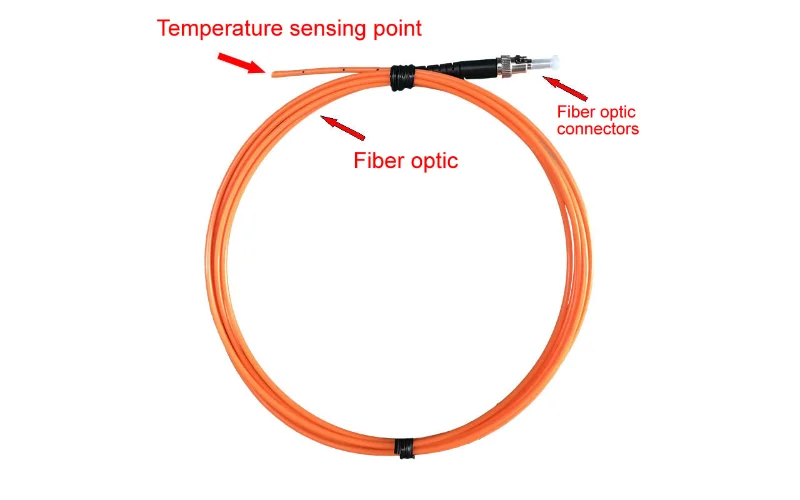
The sensing tip contains rare earth fluorescent material. When the transmitter sends an excitation light pulse through the quartz fiber, the fluorescent material emits a return signal whose decay time varies precisely with temperature. The transmitter measures this decay time and converts it to an accurate temperature reading — no electrical components, no metal conductors, no EMI interference at the measurement point.
This is the core reason why fiber optic temperature sensors have become the standard solution for monitoramento de pontos quentes em transformadores e transformer winding temperature monitoring in substations worldwide.
Especificações Técnicas
| Parâmetro | Standard Specification | Customizable |
|---|---|---|
| Faixa de temperatura | −40°C to +260°C | Yes — higher range available |
| Precisão da medição | ±1°C | Yes — higher accuracy available |
| Resolução | 0,1 °C | — |
| Tempo de resposta | <1 second | — |
| Número de canais | 1 – 64 channels | Yes |
| Fiber Optic Length | 3 – 5 m (standard) | Yes — up to 80 m |
| Fiber Type | Quartz fiber optic | — |
| High Voltage Resistance | 100 kV | — |
| Communication Protocol | RS485 / Modbus-RTU | — |
| Working Voltage | CA/CC 220 V | — |
| Consumo de energia | ≤6W | — |
| Diâmetro da sonda | 2.3 mm | Yes |
| Certificações | CE, RoHS | — |
All parameters above can be confirmed or customized based on your transformer type, installation layout, and monitoring requirements. Contact our engineering team to discuss your specific configuration.
Why Transformers Need Fiber Optic Temperature Monitoring
The top oil temperature of a power transformer — measured by a traditional thermometer at the tank wall — does not represent the actual thermal stress on the windings. The hottest point inside a transformer winding can be 20°C to 40°C higher than the measured oil temperature, yet that difference goes completely undetected without direct winding sensors.
It is this gap between apparent temperature and actual winding temperature that causes premature insulation aging, unexpected failures, and shortened transformer service life. The IEC 60076-2 standard explicitly defines the concept of the winding hot spot as the critical parameter for transformer thermal management — not top oil temperature. Direct measurement with a fiber optic temperature probe placed inside the winding is the only method that provides this data in real time.
The challenge has always been getting a sensor inside a live high-voltage transformer. Metal sensors are ruled out immediately: they create ground fault paths, distort the electric field, and compromise the insulation system. Fiber optic temperature sensors solve all three problems. They contain no metal, carry no electrical current, and are fully compatible with transformer oil and insulation paper — making them the only viable technology for this application.
Oil-Immersed Transformer Winding Hot Spot Monitoring
Oil-immersed (oil-filled) power transformers represent the most demanding and most important application for fiber optic temperature monitoring. In these units, the windings operate submerged in transformer oil, which serves as both coolant and dielectric. While the oil provides effective cooling under normal conditions, localized hotspots can develop at specific points within the winding — particularly near the top of the high-voltage coil — where oil circulation is restricted or where electrical losses concentrate.
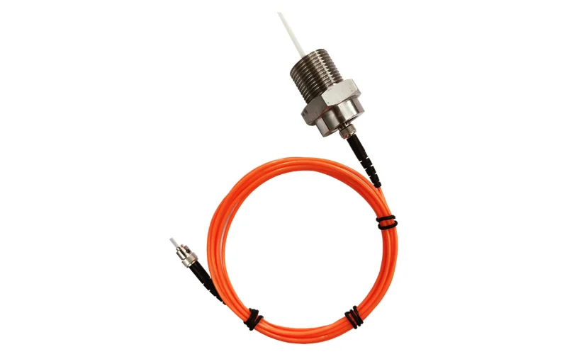
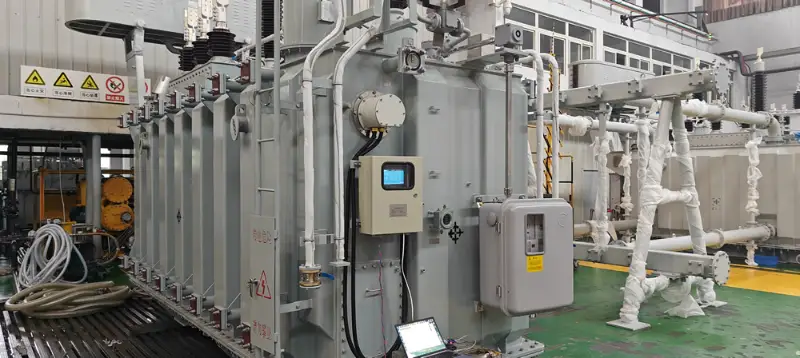
A fiber optic temperature probe with an oil-resistant construction is inserted directly into the winding during transformer assembly or major overhaul. The probe tip contacts the winding conductor or insulation paper at the location most likely to reach peak temperature. Quartz fiber optic cable runs from the winding, through a fiber optic feedthrough fitting on the transformer tank wall, to the temperature transmitter mounted on the control panel outside the tank.
This gives the protection system a direct, real-time reading of the actual winding temperature — not an estimate, not a calculated guess. When the measured temperature approaches the alarm threshold, the cooling fans ramp up. If the temperature continues to rise, a second threshold triggers a trip signal to the circuit breaker, disconnecting the transformer before insulation damage occurs.
For three-phase oil-immersed transformers, the typical installation uses 3 to 6 channels — at minimum one probe per phase winding. Larger power transformers or units with known thermal asymmetry benefit from additional probes placed at multiple heights within each winding column.
Transformer Hot Spot Monitoring and Cooling Control Integration
The real operational value of a transformer temperature monitoring system comes from integrating the winding temperature data into the transformer's protection and control logic. Most installations configure three action thresholds:
- Fan Start (e.g., 80°C): Forced cooling is activated to increase oil circulation and heat dissipation.
- Alarm (e.g., 110°C): An alert is sent to the SCADA system or control room, flagging abnormal loading conditions.
- Trip (e.g., 130°C): The transformer is disconnected to prevent insulation breakdown.
Threshold values vary based on transformer insulation class and oil type. Our transmitters communicate via RS485 / Modbus-RTU, making integration with existing transformer monitoring systems, protection relays, and SCADA platforms straightforward. The 6W power consumption means the transmitter can be powered from standard control panel auxiliary supply.
Transformer Condition Monitoring: What the Temperature Data Tells You
Real-time winding temperature is not just a protection parameter — it is a primary indicator of overall transformer health. A well-functioning monitoramento do estado dos transformadores program uses historical temperature trend data to identify developing problems before they cause failures.
If the winding temperature rises faster than expected for a given load, it may indicate oil circulation problems — blocked cooling ducts, failing oil pump, or cooling radiator fouling. If the temperature asymmetry between phases increases over time, it may indicate unbalanced loading or a developing internal fault. If the peak daily temperature is trending upward over months while loading remains constant, it may point to gradual insulation deterioration increasing thermal resistance.
This kind of monitoramento online de transformadores converts a simple temperature measurement into a predictive maintenance signal — the foundation of a condition-based maintenance program that reduces unplanned outages and extends asset life.
Large Power Transformers vs. Distribution Transformers
The monitoring configuration differs significantly between transformer classes. Large power transformers (typically 10 MVA and above, operating at 35 kV to 500 kV) are always candidates for full fiber optic winding temperature monitoring. These units are expensive, critical to grid stability, and usually installed with long fiber runs (10 m to 40 m) from the winding to control room equipment. Multi-channel configurations (6 to 16 channels) provide comprehensive thermal mapping across primary, secondary, and sometimes tertiary windings.
For distribution transformers (typically below 10 MVA), single-channel or 3-channel configurations are common, focused on the highest-stress winding only. Standard 3 m to 5 m fiber lengths usually suffice for pole-mount or pad-mount installations. The key justification for monitoring distribution transformers is typically loss-of-life calculation and dynamic loading capacity management rather than immediate fault protection.
Monitoramento da temperatura de transformadores do tipo seco
Dry-type (air-insulated) transformers are increasingly common in indoor commercial and industrial installations: data centers, hospitals, high-rise buildings, and manufacturing facilities. Because they use air or resin insulation rather than oil, there is no liquid thermal buffer — winding temperature rises directly and rapidly when loading increases or cooling airflow is obstructed.
For dry-type transformers, the fiber optic temperature probe is embedded within the resin-cast winding or placed in direct contact with the coil surface. The installation is typically done during transformer manufacturing, with fiber cables routed to external connectors on the transformer enclosure. Retrofitting is possible on open-core dry-type units during scheduled maintenance.
Dry-type transformer applications typically require 3-channel configurations (one per phase), with standard fiber lengths of 3 m to 5 m. The same RS485 / Modbus-RTU output connects directly to the building management system (BMS) or the transformer's existing temperature controller, replacing or supplementing conventional bimetallic sensors with far more accurate optical measurement.
Compared to bimetallic or PT100 sensors commonly factory-fitted on dry-type transformers, fiber optic sensors provide faster response, higher accuracy, and complete immunity to the electromagnetic fields generated by the transformer windings — eliminating the measurement errors that often affect conventional electronic sensors mounted directly on transformer coils.
Customization Options
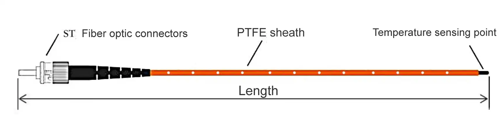
Every transformer installation presents different physical constraints, operating conditions, and monitoring objectives. Our engineering team provides customized fiber optic temperature probe configurations to match your exact requirements.
Fiber Optic Cable Length (Standard 3–5 m, up to 80 m)
The fiber length determines how far the transmitter can be located from the measurement point. Large substation transformers may require 20 m to 40 m runs from the winding through the tank wall and across the bay to the control panel. Compact 3 m lengths suit dry-type transformers where the transmitter mounts directly on the enclosure.
Oil Resistance and Probe Construction
Probes for oil-immersed transformers use materials and sealing methods fully compatible with transformer mineral oil, ester oil, and silicon oil. The probe tip, housing, and fiber optic jacket are all rated for continuous oil immersion at operating temperature. This is a mandatory requirement for any probe used in oil-filled equipment.
Probe Diameter (Standard 2.3 mm)
Standard 2.3 mm diameter suits most winding installation scenarios. Smaller diameters are available for tight winding gaps. Larger diameters can be specified for applications requiring greater mechanical strength or longer thermal equilibration times.
Number of Channels (1–64)
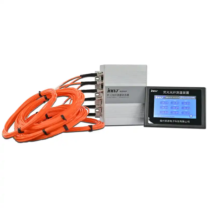
Single-channel units monitor one critical winding point. Three to six channels cover a complete three-phase transformer. Higher channel counts (8 to 16) provide detailed thermal mapping for large power transformers or units with complex winding geometry. Up to 64 channels can be integrated into a single transmitter for multi-transformer substation monitoring from a centralized panel.
Temperature Range and Accuracy
The standard −40°C to +240°C range covers all normal and fault-condition temperatures encountered in power transformers. Higher upper limits are available for specialized applications. Standard ±1°C accuracy is sufficient for protection and condition monitoring. Tighter accuracy specifications can be configured for applications requiring high-precision thermal analysis.
System Components Overview
A complete fiber optic temperature monitoring system for transformer applications consists of three main components working together:
Fluorescent Sensing Probe
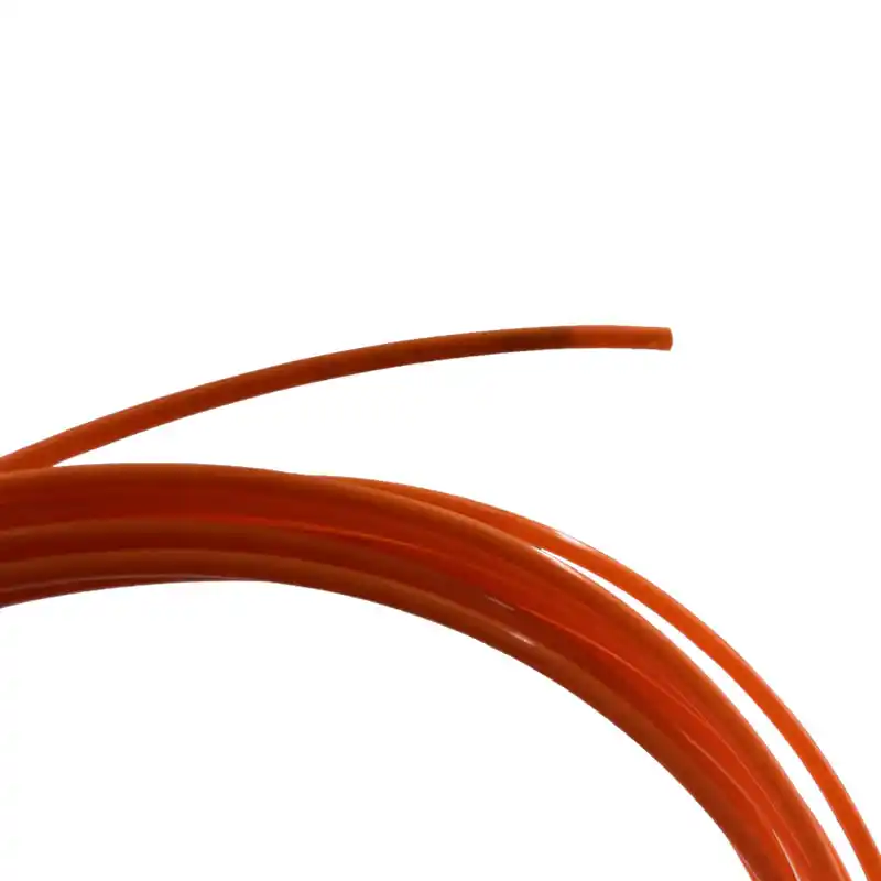
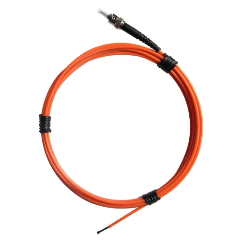
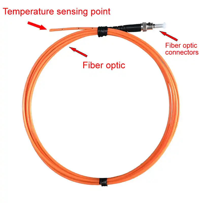
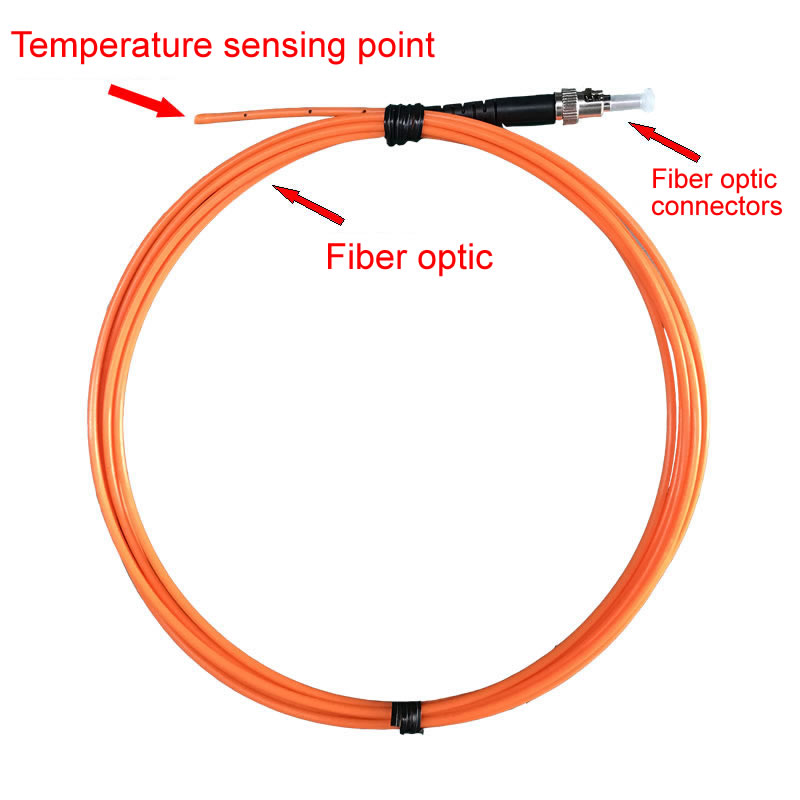
The probe is the element that physically contacts the winding. It contains the rare earth fluorescent crystal in a sealed housing. For oil-immersed transformers, the housing is rated for full oil immersion. The probe connects to the fiber optic cable via a low-loss optical joint designed to maintain signal quality over years of service inside a transformer tank.
Quartz Fiber Optic Cable
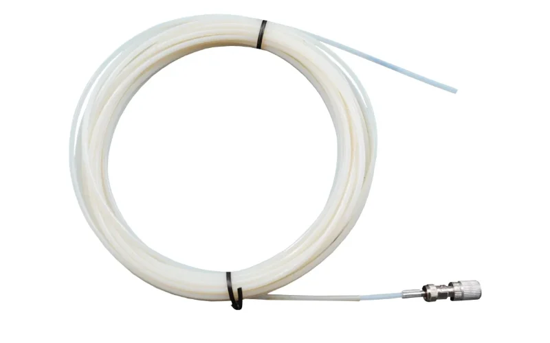
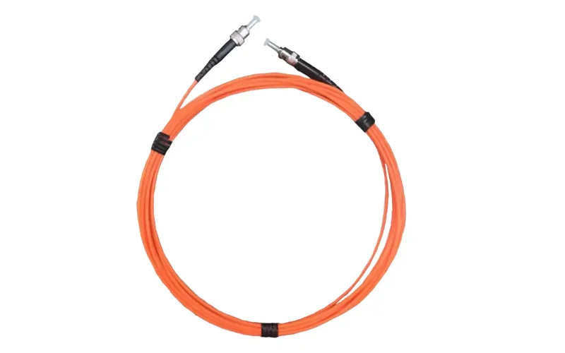
High-purity quartz fiber transmits the optical signal between the probe and the transmitter with minimal attenuation. The cable jacket material is selected for compatibility with the installation environment — transformer oil for submersed runs, armored jacket for surface routing, LSZH jacket for indoor control panel areas. Custom lengths from 3 m to 80 m are manufactured to order.
Temperature Transmitter (Signal Processor)
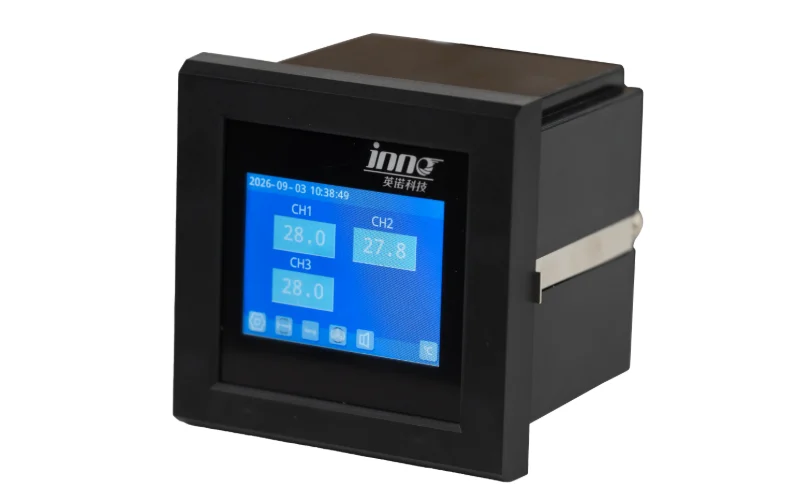
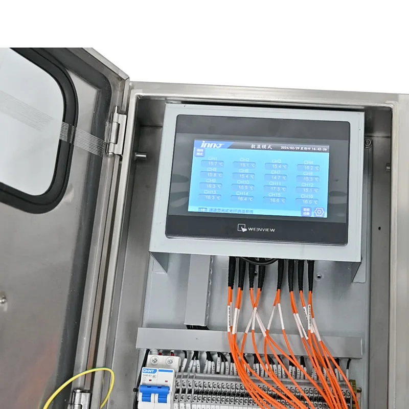
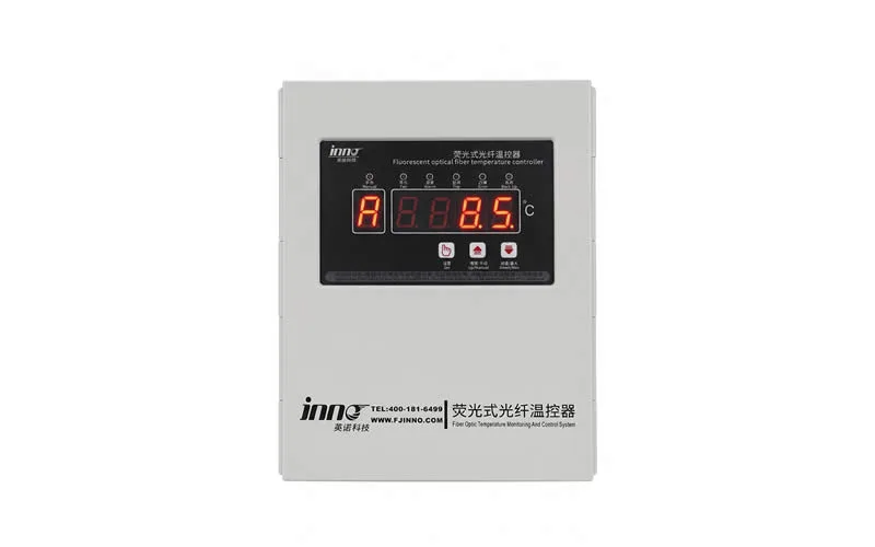
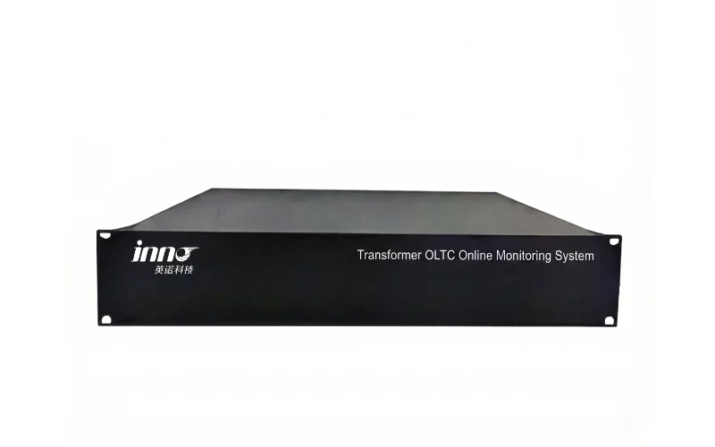
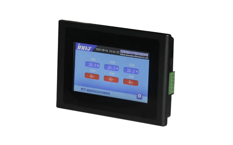
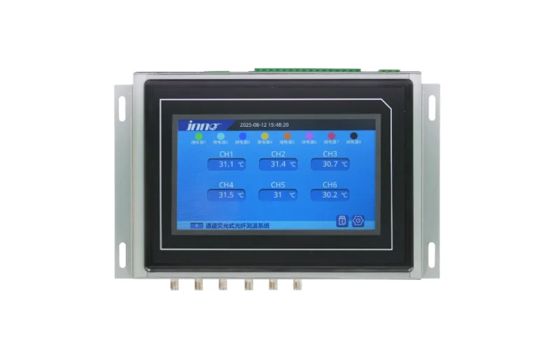
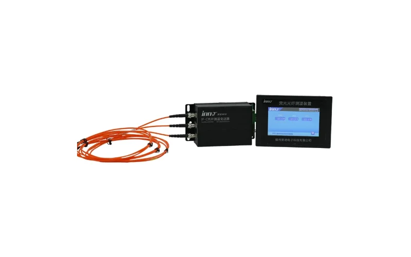
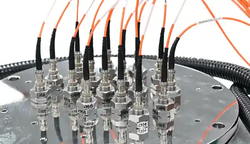
The transmitter generates the excitation light pulses, receives and processes the fluorescence return signal, calculates temperature from decay time, displays readings on the front panel, and outputs data via RS485 / Modbus-RTU. Multi-channel transmitters process signals from 1 to 64 probes simultaneously. Relay outputs for fan start, alarm, and trip can be configured directly on the transmitter, or the Modbus data can be used by the upstream protection relay or SCADA system.
Recommended Channel Configurations for Transformer Applications
| Tipo de transformador | Recommended Channels | Typical Probe Placement | Comprimento da fibra |
|---|---|---|---|
| Distribution transformer (<10 MVA) | 1 – 3 channels | HV winding top (hottest point per phase) | 3 – 5 m |
| Medium power transformer (10–63 MVA) | 3 – 6 channels | HV and LV winding tops, all three phases | 5 – 20 m |
| Large power transformer (>63 MVA) | 6 – 16 channels | HV/LV windings at multiple heights, all phases | 10 – 40 m |
| Dry-type transformer (any rating) | 3 channels | One per phase, coil surface or embedded in resin | 3 – 5 m |
| Multi-transformer substation bay | Up to 64 channels | Distributed across all transformers, centralized transmitter | Up to 80 m |
Perguntas frequentes
What is the difference between winding hot spot temperature and top oil temperature?
Top oil temperature is measured at the surface of the transformer oil using a conventional thermometer pocket on the tank. It reflects the bulk oil temperature — a useful but indirect indicator. Winding hot spot temperature is the actual peak temperature inside the winding conductor at its most thermally stressed point. IEC 60076-2 defines the hot spot as the determining parameter for transformer insulation aging. In typical loading conditions, the hot spot can exceed top oil temperature by 20°C to 40°C. Only a fiber optic temperature sensor placed directly in the winding provides this reading.
Can the fiber optic probe survive continuous immersion in transformer oil?
Yes — provided the correct oil-resistant probe construction is specified. Our probes for oil-immersed transformer applications use materials, adhesives, and sealing methods fully rated for long-term immersion in mineral transformer oil, natural ester oil, and silicone oil. The quartz fiber itself is chemically inert in oil environments. Probe service life in oil-immersed applications typically matches or exceeds the transformer's major maintenance interval.
Does installation require taking the transformer offline?
For oil-immersed transformers, probe installation is typically performed during factory assembly (preferred), or during scheduled outage when the transformer is drained for major maintenance. Retrofitting a probe into an energized, oil-filled transformer is not standard practice. For dry-type transformers, probes can be added during a scheduled de-energization without full disassembly in many cases.
How does the 100 KV high voltage resistance work?
The quartz fiber optic cable and probe housing contain no metallic conductors. The fiber transmits optical signals only — light, not electricity. This means there is no conductive path between the winding (which may be at tens or hundreds of kilovolts) and the transmitter at ground potential. The 100 KV rating confirms that the fiber optic assembly has been tested to withstand this voltage difference without dielectric breakdown, meeting the insulation requirements for high-voltage transformer applications.
How many probes do I need for a three-phase oil transformer?
The minimum recommended configuration is three probes — one per phase, placed at the top of the high-voltage winding where temperatures are highest. For more comprehensive monitoramento da temperatura do transformador, a 6-channel configuration adds a second probe per phase at the low-voltage winding. Large or critical transformers may use 9 to 16 probes to map the thermal profile at multiple heights across all windings.
What communication protocol does the transmitter use?
Standard transmitters output RS485 / Modbus-RTU, the most widely used protocol in industrial automation and power system equipment. This allows direct integration with transformer protection relays, substation RTUs, SCADA systems, and building management systems without additional protocol converters. Register maps and integration documentation are provided with every transmitter.
Can the system trigger cooling fans and protection relays automatically?
Yes. The transmitter includes configurable relay output contacts that can be wired directly to the transformer's fan contactor (fan start), alarm panel (warning), and protection relay (trip). Three independent relay thresholds are standard. Alternatively, the Modbus output can carry the temperature data to the upstream protection relay, which handles the switching logic based on its own configuration.
What is the difference between fiber optic sensors and PT100 sensors for transformer monitoring?
PT100 resistance temperature detectors require metal conductors running to the measurement point, making them incompatible with direct winding contact in high-voltage transformers. They are also susceptible to measurement errors induced by the strong electromagnetic fields present near transformer windings. Fiber optic sensors are all-dielectric (no metal), are fully immune to electromagnetic interference, and can be safely placed in direct contact with energized winding conductors. For winding hot spot measurement, fiber optic sensing is the only technically viable option.
Is the accuracy of ±1°C sufficient for transformer protection?
Yes, for the vast majority of transformer protection and condition monitoring applications. IEC and IEEE transformer protection standards define alarm and trip thresholds with 5°C to 10°C margins, well within the ±1°C accuracy range. For applications requiring tighter accuracy — such as detailed loss-of-life calculations or research-grade thermal modeling — we can configure higher-accuracy variants. Contact our engineering team to discuss your specific accuracy requirements.
Can the fiber optic cable length be extended after installation?
Yes, within limits. Optical extension cables can be spliced using fiber optic connectors to increase the distance between probe and transmitter. Signal loss increases with cable length, so extensions beyond the standard range should be reviewed by our technical team to confirm the signal budget remains within specification. For new installations, it is always preferable to specify the correct fiber length at the time of order rather than adding extensions later.
Do you supply complete transformer monitoring systems or probes only?
We supply complete fiber optic temperature monitoring systems including probes, fiber optic cables, transmitters, mounting hardware, and installation documentation. We also supply individual components for integration into existing systems or for replacement of damaged parts. Custom configurations — including specific fiber lengths, probe constructions, and channel counts — are available from our factory with standard lead times.
What certifications do your products carry?
Our fiber optic temperature sensors and transmitters carry CE certification (EU safety and EMC directives) and RoHS certification (restriction of hazardous substances). Products are manufactured under an ISO 9001 quality management system. Test reports documenting accuracy verification, response time, and high-voltage insulation testing are provided with each shipment.
Why Choose INNO Fiber Optic Temperature Sensors
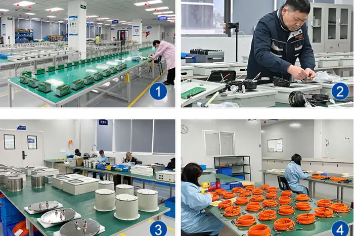
We are a dedicated manufacturer of fluorescent fiber optic temperature measurement equipment, specializing in transformer and power equipment applications. Our products are supplied factory-direct — no distributors, no markups — with full OEM and ODM capability for customers requiring branded or application-specific configurations.
Every system is configured to your transformer's specific requirements: fiber length, probe construction, channel count, oil compatibility, and communication integration. Our engineering team is available to review your installation drawings, confirm the correct probe placement, and provide commissioning support remotely.
CE and RoHS certified. ISO 9001 manufacturing. Shipped globally with full documentation.
Contact us with your transformer specifications to receive a detailed configuration recommendation and quotation.