

Surveillance des décharges partielles dans les transformateurs : méthodes de détection, capteurs et surveillance en ligne
发布时间:24 septembre 2026, 12 h 36 min 05 s
Partial discharge (PD) is a localized electrical discharge within or around an insulation system that does not completely bridge the insulation between conductors. In a transformer, PD can point to localized insulation defects, and persistent or increasing activity can contribute to insulation deterioration over time. This guide covers the physics, the detection methods, the sensors, and the practical planning of a partial discharge monitoring system for transformers.
- PD is a localized discharge that does not cause complete insulation breakdown, but sustained activity can progressively damage insulation.
- Detecting PD does not by itself identify the exact defect. Interpretation requires location, pattern, trend, operating condition and other transformer condition data.
- UHF, HFCT, acoustic and conventional electrical methods each detect a different physical signal and suit different transformer designs and site conditions.
- Sensor type, number and position depend on transformer construction and the access points available.
- Online monitoring and periodic or offline testing serve different purposes and can complement each other.
- PD is one condition indicator within a wider partial discharge monitoring and asset-management strategy.
What Is Partial Discharge in a Transformer?
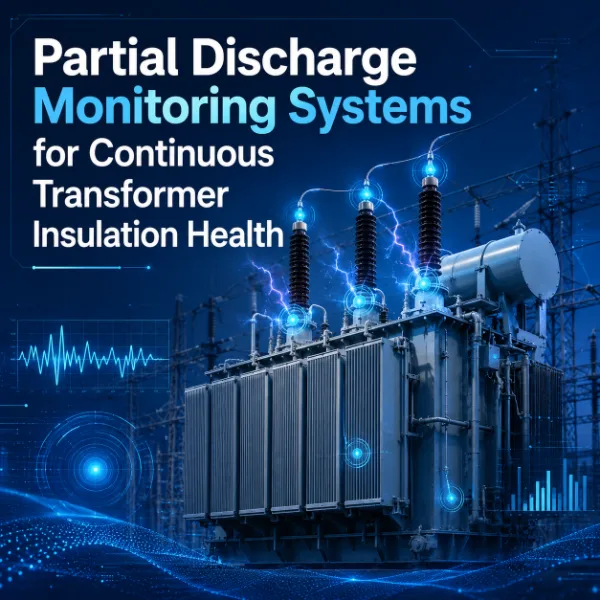
Partial discharge is a localized electrical discharge that occurs where the electric field exceeds the local withstand capability of a small region of insulation. Because the discharge only partially bridges the insulation between conductors, the transformer continues to operate. The discharge itself is small in energy, but it repeats with each voltage cycle, and the cumulative effect can be significant.
In a transformer, PD may occur:
- inside the insulation, for example in a void or defect in solid insulation or in a gas bubble in oil;
- at interfaces between different insulating materials, such as oil and pressboard;
- around high-field regions, such as sharp conductive points, electrode edges or poorly graded components.
Sustained PD can degrade the surrounding insulation through localized heating, chemical decomposition and erosion. The rate and consequence depend on the discharge energy, the location, the insulation material and the operating stress.
Partial Discharge vs. Breakdown vs. Noise
Three phenomena are often confused during measurement:
- Partial discharge: a localized discharge that leaves the insulation system in service. It can be intermittent or persistent.
- Complete electrical breakdown: a discharge that fully bridges the insulation between conductors, producing a fault.
- External electrical noise: signals that resemble PD but do not originate from a transformer insulation defect, such as radio interference, switching transients or corona on external hardware.
Separating genuine PD from noise is one of the central practical challenges of PD measurement, particularly during online operation.
What Causes Partial Discharge in Transformers?
PD arises when local electric stress is high relative to the local insulation condition. Which mechanisms are relevant depends on the transformer design, the insulation system and the operating history. The following conditions are commonly associated with PD activity, although none of them necessarily produces PD in every transformer:
- Voids or defects in solid insulation, which can arise from manufacturing or from thermal and mechanical stress.
- Insulation interfaces, where differences in permittivity or poor contact can concentrate the field.
- Contamination, including particles or other impurities in oil or on insulation surfaces.
- Moisture-related insulation degradation, which can reduce dielectric strength and change the conditions for discharge.
- Sharp conductive points or field concentrations, such as burrs, edges or poorly shaped electrodes.
- Loose or floating conductive components, which can develop a potential different from their surroundings.
- Degraded insulation, including aging-related deterioration of cellulose or other materials.
- Problems around bushings or connections, where insulation and field grading are complex.
- Manufacturing defects, introduced during assembly, drying or oil processing.
Oil-immersed and dry-type transformers have different insulation systems and therefore different dominant PD mechanisms. For a broader view of how insulation-related problems fit among other failure mechanisms, see this guide to transformer failure modes.
Why Is Partial Discharge Monitoring Important?
PD monitoring supports several aspects of asset management:
- Insulation condition assessment: PD activity provides information about the localized dielectric condition that other measurements may not reveal.
- Early detection of developing dielectric problems: changes in PD behavior may appear before other indicators change noticeably.
- Trending of abnormal activity: continuous or repeated measurement shows whether activity is stable, intermittent or increasing.
- Maintenance planning: PD information can help prioritize inspection, testing or intervention.
- Investigation of suspect transformers: monitoring can help confirm or rule out PD when other tests raise questions.
- Correlation with other condition data: PD results are more meaningful when compared with gas, temperature, moisture and load data.
PD monitoring alone does not predict transformer failure. It should be treated as one indicator within a wider surveillance de l'état des transformateurs strategy. Where the focus is dielectric health, it is a natural part of transformer insulation monitoring.
Partial Discharge Detection Methods for Transformers
PD produces several measurable physical effects: high-frequency current pulses, electromagnetic radiation, acoustic waves, and chemical changes in the insulating medium. Each detection method targets one of these. The table below summarizes the main approaches.
| Detection Method | Signal Detected | Typical Sensor / Connection | Main Advantages | Key Limitations / Considerations | Exemple d'application |
|---|---|---|---|---|---|
| UHF detection | Electromagnetic waves radiated by PD | UHF sensor inside or at the tank, through a suitable access point, dielectric window or purpose-designed interface | Can offer good rejection of external electrical noise, since the tank acts as a partial shield; supports multi-sensor localization | Installation depends strongly on transformer construction and available access; internal structures affect signal propagation | Online monitoring and diagnostic investigation of oil-immersed power transformers where suitable access exists |
| HFCT / high-frequency current detection | High-frequency current pulses associated with PD | High-frequency current transformer clamped on a suitable grounding or measurement connection | Non-intrusive installation is possible where a suitable connection is accessible; useful for online detection | Susceptible to external interference on the connection; suitable installation points differ between transformers | Online detection on transformers, bushing tap or grounding connections where installation allows |
| Acoustic emission | Ultrasonic / acoustic energy from PD | Acoustic sensors mounted externally on the tank surface | External, non-intrusive mounting; immune to electromagnetic interference; multiple sensors can help approximate source location | Attenuation through oil, windings and tank structure; sensitivity depends on source location and transformer geometry; mechanical noise must be considered | Source localization and supplementary confirmation on oil-immersed transformers |
| Conventional electrical PD measurement | Apparent charge from PD pulses, measured through a coupling circuit | Coupling capacitor and measuring impedance, or bushing tap adaptors, used with a calibrated measuring system | Established approach for factory, commissioning and offline diagnostic testing; calibrated procedure | Typically requires an outage and test supply; a controlled test environment differs from in-service conditions | Factory acceptance tests, commissioning and offline diagnostic tests |
| Dissolved gas analysis (indirect) | Gases dissolved in the insulating oil | Oil sampling or online gas monitor | Provides evidence of electrical or thermal activity over time | Does not measure PD directly and does not locate the source | Complementary indicator of possible electrical activity, used alongside PD measurement |
UHF Partial Discharge Detection
Each PD event produces a very fast current pulse, which radiates electromagnetic energy over a wide frequency range, including the ultra-high-frequency (UHF) band. A UHF sensor is essentially an antenna that captures this radiation. Because the grounded tank provides some shielding, UHF detection can be an advantage in electrically noisy environments, since much external interference is attenuated before it reaches an internal or tank-mounted sensor.
UHF installation depends strongly on transformer design. Depending on the unit, sensors may use suitable existing access points, dedicated dielectric windows, or purpose-designed interfaces provided by the manufacturer. The available method must be established for each transformer, and cannot be assumed from one unit to another. Signal propagation inside the tank is also affected by internal structures such as windings, core and barriers, which influences both sensitivity and localization.
HFCT Partial Discharge Detection
A PD event also produces high-frequency current pulses that travel through the transformer and connected conductors. A high-frequency current transformer (HFCT) can detect these pulses when clamped around a suitable conductor, such as a grounding connection or another measurement connection that carries the PD current.
HFCT sensors can be useful for online detection where installation allows, and they are often non-intrusive. However, installation is not identical on every transformer: available connection points differ with design, bushing arrangement and grounding practice. Because HFCT signals travel on conductors, external electrical interference coupled through these connections must be considered and separated from PD signals during analysis.
Acoustic Partial Discharge Detection
PD generates a small pressure disturbance, which propagates as ultrasonic or acoustic energy through the insulating medium and the transformer structure. Acoustic sensors can be installed externally on the tank surface, without direct access to the internal volume.
Using multiple sensors and comparing signal arrival times can assist with approximate source localization. Acoustic detection is not affected by electromagnetic interference, although mechanical or ambient noise can affect it. Attenuation through oil, windings and tank structure, and the transformer's internal geometry, influence what can be detected. Acoustic results are often most useful for locating and supporting the interpretation of PD detected by another method.
Conventional Electrical Partial Discharge Testing
Conventional electrical PD measurement is widely used in factory testing, commissioning and offline diagnostic testing. It uses a calibrated measuring circuit to quantify apparent charge from PD pulses, typically during a controlled voltage application while the transformer is out of service.
Online and offline PD measurements serve different purposes and should not be treated as identical. Offline testing is applied under controlled conditions with a defined test procedure, while online monitoring observes the transformer in service under actual operating and noise conditions. Results from the two approaches are not directly interchangeable.
Tests de décharges partielles en ligne et hors ligne
| Aspect | Online PD Monitoring | Offline PD Testing |
|---|---|---|
| Operating condition | Transformer in normal service, under actual load and voltage | Transformer de-energized from service and energized under test conditions |
| Measurement duration | Continuous or repeated over long periods | Limited to the test period |
| Outage requirement | No outage needed for measurement; some installations may need one for sensor fitting | Outage required |
| Noise environment | Site noise present and must be identified and separated | More controlled, though not always noise-free |
| Ability to observe trends | Strong, since data accumulates over time | Limited to intervals between tests |
| Diagnostic depth | Depends on sensors and analysis; detailed investigation may need additional tests | Can allow controlled voltage variation and detailed investigation |
| Installation requirements | Permanent sensors and acquisition equipment | Test equipment brought to site or performed in a test bay |
| Typical use | Ongoing condition monitoring and trending | Factory acceptance, commissioning, periodic or investigative diagnostics |
Neither approach always replaces the other. Permanent online monitoring can flag changes and provide trend context, while periodic or offline testing can provide controlled, more detailed diagnostic information when needed. The two are often used together.
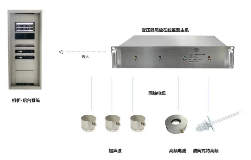
What Sensors Are Used for Transformer Partial Discharge Monitoring?
UHF Sensors
- Physical signal measured: electromagnetic radiation emitted by PD events in the UHF band.
- Typical installation: at a suitable access point on the tank, through a dielectric window, or through an interface designed for UHF sensing. Some sensors extend into the oil volume, while others are external, depending on design.
- Selection factors: the availability of suitable access points, tank and internal construction, whether the interface was designed into the transformer, and the required number of sensors for localization.
HFCT Sensors
- Physical signal measured: high-frequency current pulses associated with PD.
- Typical installation: clamped around a grounding conductor or another suitable measurement connection, without cutting the conductor in the case of split-core designs.
- Selection factors: which conductors are accessible and carry the relevant signal, grounding arrangement, bushing configuration, and the level of external interference on those connections.
Acoustic Sensors
- Physical signal measured: ultrasonic or acoustic energy from PD, transmitted through the transformer structure.
- Typical installation: mounted externally on the tank wall, often in an array of several sensors.
- Selection factors: tank size and geometry, internal structures affecting propagation, the need for source localization, and the level of mechanical and ambient noise.
Conventional Electrical Coupling Devices
- Physical signal measured: electrical PD pulses, quantified as apparent charge through a calibrated circuit.
- Typical installation: connected through a coupling capacitor or a bushing tap adaptor, as part of a defined test setup.
- Selection factors: availability of a suitable connection, test voltage supply, outage availability, and whether calibrated measurement is required, as in acceptance testing.
Where sensitivity, frequency range or accuracy figures matter, these should be taken from the sensor and system documentation for the specific installation, since they vary between designs and cannot be generalized.
How Does an Online Transformer Partial Discharge Monitoring System Work?
An online PD monitoring system carries the signal from its source to the operator through a chain of stages:
PD source → sensor → signal acquisition → filtering / noise suppression → signal processing → PD pattern / trend analysis → alarm or event → local monitoring device → communication → SCADA / centralized monitoring
- Sensor: converts the physical PD signal (electromagnetic, current or acoustic) into an electrical signal.
- Signal acquisition: digitizes the sensor output, usually synchronized with the power-frequency cycle so that phase relationships can be analyzed.
- Filtering and noise suppression: reduces the influence of interference before and during analysis.
- Signal processing and pattern / trend analysis: extracts characteristics such as magnitude, repetition rate and phase pattern, and tracks them over time.
- Alarm or event: flags conditions that meet configured criteria, which are set according to the specific transformer and site.
- Local monitoring device and communication: stores data and events locally and passes information to remote systems.
- SCADA or centralized monitoring: makes results available to operators and maintenance teams.
In practice, a system has to separate possible PD signals from other sources of high-frequency energy, including:
- radio interference;
- switching noise;
- corona outside the transformer;
- communication equipment;
- other high-frequency electromagnetic noise.
Noise rejection relies on the choice of sensor, measurement bandwidth, filtering, and comparison between multiple sensors or channels. Results still require engineering review, since automated processing does not remove the need to confirm whether an event is a genuine PD signal. A dedicated système de surveillance en ligne des décharges partielles des transformateurs brings these stages together in one architecture, though the sensor configuration should still be matched to the transformer.
How Is Partial Discharge Data Interpreted?
Interpreting PD data requires more than reading a single number. Several factors should be considered together:
- Magnitude is not enough. A large or small reading alone does not establish severity, since it depends on the source, location, sensor and signal path.
- Trend over time matters. Stable, intermittent and rising activity can have very different implications.
- Repetition rate matters. How often discharges occur adds information beyond amplitude.
- Phase relationship and pattern. The position of PD pulses relative to the power-frequency cycle can help suggest the type of source, though patterns are not always unambiguous.
- Behavior under different load and voltage conditions. Changes in PD activity as operating conditions vary provide useful context.
- Multi-sensor correlation. Agreement between sensors, or between different methods, can raise confidence that a signal is genuine PD.
- Location information. Even approximate localization helps distinguish between possible sources, such as an internal defect versus an external one.
- Noise identification. Signals must be assessed for possible interference before being attributed to the transformer.
Actual diagnosis requires engineering interpretation, taking into account the transformer design, history and operating conditions. This article does not give universal alarm thresholds, because appropriate criteria depend on the transformer, sensor type, site and measurement method.
Partial Discharge and Other Transformer Condition Indicators
PD data is more informative when evaluated together with other condition data. The table summarizes typical combinations.
| Combination | What It Can Add | Caution |
|---|---|---|
| PD + DGA | Trends in hydrogen or other relevant gases may support evidence of electrical activity when PD is also detected | DGA does not measure PD directly and cannot locate the source |
| PD + Temperature | Unusual thermal conditions provide context for changes in insulation behavior | Temperature and PD are separate phenomena and may not be related |
| PD + Bushing Condition | Helps identify whether abnormal insulation behavior may be associated with a bushing | Bushing monitoring and PD monitoring measure different things |
| PD + Moisture | Moisture can affect insulation condition and the conditions for discharge | The relationship depends on insulation design and where the moisture is located |
| PD + Load / Operating Condition | Shows when PD activity changes with load, voltage or other conditions | Correlation does not by itself establish cause |
Some of these combinations deserve more explanation:
- Gas trends. PD and transformer DGA monitoring measure different phenomena: PD detects the discharge activity itself, while dissolved gas analysis reflects gases produced in the oil. When electrical insulation activity is suspected, hydrogen and other relevant gas trends may provide complementary evidence, but they should not be read as a direct PD measurement.
- Temperature. Unusual thermal conditions, such as those tracked through transformer winding hot spot temperature measurement, add context to an overall condition assessment.
- Bushings. Transformer bushing monitoring measures bushing-specific insulation indicators and can provide additional context when abnormal insulation behavior is suspected. It is a different technology from PD monitoring, and the two are not interchangeable.
- Load and voltage. Knowing operating conditions helps explain when PD activity appears, changes or disappears.
Fault diagnosis should not be oversimplified: each indicator has its own limitations, and conclusions should rest on the combined evidence.
Partial Discharge Monitoring for Different Transformer Types
| Type de transformateur | Relevant PD Risks | Possible Detection Methods | Monitoring Considerations |
|---|---|---|---|
| Grands transformateurs de puissance | Insulation defects in high-stress regions, bushing and lead-exit areas, aging-related deterioration | UHF, HFCT, acoustic; conventional electrical testing offline | Higher criticality and voltage stress; multiple sensors may be justified; access points depend on design |
| Oil-immersed transformers | Voids, contamination, moisture, interfaces in the oil-paper system, floating components | UHF, HFCT, acoustic; DGA as a complementary indicator | Availability of oil access points or dielectric windows; tank structure affects propagation |
| Dry-type transformers | Voids or surface effects in solid or resin insulation; surface tracking in some conditions | Depends on construction; electrical detection and other methods may apply | No oil or tank shielding in the same sense; environment and enclosure conditions influence which method suits |
| Substation transformers | Depends on type and voltage level; external corona and site noise are common considerations | Depends on type; HFCT, UHF or acoustic where suitable | Site noise, remote operation and communication needs; suitability for unattended monitoring |
Monitoring configuration depends on transformer construction, insulation system, voltage level, accessibility and criticality. For high-value units, the broader context of surveillance des transformateurs de puissance helps determine how PD fits alongside other measurements.
When Is Online Partial Discharge Monitoring Most Useful?
Permanent online monitoring is not required for every transformer, but it can be particularly useful in cases such as:
- critical power transformers;
- high-voltage transformers;
- transformers with abnormal test results;
- transformers with known insulation concerns;
- units where periodic testing has indicated possible PD;
- remote or unattended substations;
- high-consequence industrial installations;
- assets where an unplanned outage would have a significant operational impact.
The decision should balance asset criticality, risk, evidence of insulation concerns and the cost and practicality of installation. For many transformers, periodic testing and other condition indicators may be sufficient.
Comment choisir un système de surveillance des décharges partielles des transformateurs
The following checklist supports an engineering-led selection process. It avoids fixed specifications, since suitable values depend on the specific application.
- Transformer type: oil-immersed, dry-type, power, or substation unit.
- Voltage class: as it relates to insulation stress and available access.
- Insulation design: materials, structure and likely PD mechanisms.
- Transformer criticality: consequences of an unplanned outage.
- Existing evidence of PD: prior test results, gas trends or other indications.
- Available sensor installation points: access points, dielectric windows, grounding connections and tank surfaces.
- Preferred detection method: UHF, HFCT, acoustic, or a combination, based on the above.
- Number and location of sensors: driven by coverage and localization needs.
- Site electrical noise: known interference sources and how they may affect measurements.
- Required source localization capability: whether detection alone is sufficient or location is needed.
- Local alarms: what alarm outputs and event handling are needed at the substation.
- Communication and SCADA requirements: interfaces and protocols required by the utility or plant.
- Installation and outage constraints: whether sensor fitting can be done in service or needs an outage.
- Data storage and trend requirements: how long data should be retained and how it will be reviewed.
- Future maintenance and diagnostic workflow: who reviews the data, and how follow-up testing will be triggered.
For a broader view of where PD sits among failure mechanisms and detection approaches, see the guide to transformer failure modes. When a transformer has been evaluated against the criteria above, an online partial discharge monitoring system for transformers can be matched to the identified sensor options and site conditions.
Partial Discharge Monitoring and SCADA Integration
At a general level, integration involves the following elements:
- Local monitoring device: acquires and processes sensor data and stores it locally.
- Alarm outputs: provide local indication or signal to other systems when configured conditions are met.
- Communication interface: connects the local device to the site or utility network.
- Remote monitoring: allows engineers to review data without visiting the substation.
- SCADA integration: makes selected values, alarms and status available to the control system.
- Event records: preserve information about detected events for later review.
- Long-term trends: support review of changes over months and years.
Common industrial protocols may be used for communication, but actual protocol support depends on the specific product configuration and should be confirmed for the system being considered. Integration requirements should be defined early, together with the site's cybersecurity and network policies.
Transformer Partial Discharge Monitoring Implementation Checklist
- Define the transformer and insulation system.
- Review asset history and previous diagnostic results.
- Identify suspected failure mechanisms.
- Evaluate site electrical noise.
- Select the appropriate PD detection method.
- Determine sensor locations and channel count.
- Define acquisition and monitoring architecture.
- Define communication and SCADA requirements.
- Install and commission the system.
- Establish baseline PD behavior.
- Verify noise sources.
- Review trends periodically.
- Use additional diagnostic testing when required.
Foire aux questions
What is partial discharge in a transformer?
Partial discharge is a localized electrical discharge within or around the insulation system that does not completely bridge the insulation between conductors. It can indicate a localized insulation defect, and sustained activity can contribute to insulation deterioration.
What causes partial discharge in transformers?
Contributing conditions include voids or defects in solid insulation, insulation interfaces, contamination, moisture-related degradation, sharp conductive points, loose or floating components, degraded insulation, problems near bushings or connections, and manufacturing defects. Which of these apply depends on the transformer design and insulation system.
How is partial discharge detected in a transformer?
PD can be detected through the electromagnetic radiation it produces (UHF), high-frequency current pulses (HFCT), acoustic emission, or conventional electrical measurement of apparent charge. The appropriate method depends on transformer construction, access points and site conditions.
What is the difference between online and offline partial discharge testing?
Online monitoring observes the transformer in service under real operating and noise conditions, and supports trending. Offline testing is performed with the transformer out of service under controlled conditions, and is used for acceptance, commissioning and detailed diagnostics. They serve different purposes and can complement each other.
Which sensors are used for transformer PD monitoring?
Common options are UHF sensors, HFCT sensors, acoustic sensors and conventional electrical coupling devices. Each measures a different physical signal, and selection depends on transformer design and available installation points.
Can partial discharge monitoring detect the exact location of a fault?
Not necessarily. Multi-sensor systems, particularly acoustic or UHF arrays, may help estimate the approximate source location, but accuracy depends on the method, transformer structure and signal conditions. Confirming the actual defect generally requires further diagnostics and engineering judgment.
Does every transformer need online partial discharge monitoring?
No. Online monitoring is most useful for critical, high-voltage or high-consequence transformers, units with abnormal test results or known insulation concerns, and remote installations. For other transformers, periodic testing and other condition indicators may be adequate.
Can partial discharge monitoring be integrated with SCADA?
Generally, monitoring devices can provide alarms, status and data to SCADA through a communication interface. The specific protocols and features depend on the product configuration and should be confirmed for the chosen system.
Conclusion
Partial discharge is an important indicator of transformer insulation condition, but no single PD measurement should be interpreted in isolation. Detection method and sensor selection depend on transformer design and installation conditions, and online monitoring and offline diagnostics are complementary rather than interchangeable. Trending, noise identification and correlation with other transformer condition data, such as gas analysis, temperature, bushing condition and load, are central to drawing reliable conclusions.
For readers evaluating a monitoring approach, further information is available on online partial discharge monitoring solutions.







