
What Is Transformer Oil Dissolved Gas Analysis?
Why Utilities and Industrials Choose INNOFZ DGA Monitoring
Continuous Online DGA Monitoring with ≤ 2-Hour Sampling Cycle
The system cycles through oil extraction, vacuum degassing, and chromatographic analysis automatically. A sub-2-hour cycle time means rapidly developing faults — such as arc discharge that evolves over hours — are caught while corrective action is still possible. Unlike periodic offline sampling, there are no blind intervals between measurements.
Dynamic Vacuum Degassing for High-Accuracy Dissolved Gas Extraction
A proprietary dynamic vacuum membrane degassing unit strips dissolved gases from transformer oil with consistent efficiency regardless of oil temperature or viscosity. This extraction method underpins measurement repeatability and eliminates the manual handling errors inherent in offline oil sampling, making it particularly suited to unattended substations and remote monitoring deployments.
Automated Fault Diagnosis — Three-Ratio Method and David Triangle Built In
Once gas concentrations are measured, the embedded analytical engine applies IEC 60599 / IEEE C57.104 interpretation algorithms — including the Doernenburg ratio, three-ratio (Rogers ratio) method, and David triangle — to classify the fault type automatically. Trend charts, alarm thresholds, and rate-of-change tracking are displayed on the integrated HMI without requiring an external DGA specialist for routine interpretation.
Long-Term Data Storage for Transformer Condition History and CBM Programs
On-board storage retains a minimum of 10 years of measurement records, enabling condition-based maintenance (CBM) programs to track transformer health over its entire operating life. Long historical datasets expose slow-developing faults — such as low-temperature cellulose degradation producing CO and CO₂ — that single-point measurements would miss entirely.
Seamless SCADA Integration via IEC 61850 and MODBUS Protocols
All gas concentrations, alarm states, device diagnostics, and trend data are transmitted via RS-485 (MODBUS RTU/TCP) and IEC 61850 MMS/GOOSE simultaneously, allowing the DGA monitor to be incorporated into any modern substation automation system or energy management platform without gateway hardware. Optional 4–20 mA analog outputs are available for legacy SCADA environments.
Hot-Oil Live Installation — No Transformer Outage Required
Commissioning requires only a connection to the transformer's oil sampling valves and a power supply. The system circulates transformer oil through its internal sampling circuit continuously, with no need to de-energize or take the transformer out of service. This makes retrofit installation practical even on critical, high-utilization transformers where scheduled outages are difficult to arrange.
Technical Specifications — Online DGA Monitor
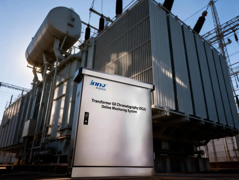
Dissolved Gas Detection Parameters and Measurement Ranges
| Gas Component | Detection Range | Précision | Repeatability (RSD) |
|---|---|---|---|
| Hydrogen (H₂) | 2 – 2,000 μL/L | ± 30% or ± 5 μL/L | ≤ 5% |
| Methane (CH₄) | 0.5 – 2,000 μL/L | ± 30% or ± 1 μL/L | ≤ 5% |
| Ethane (C₂H₆) | 0.5 – 2,000 μL/L | ± 30% or ± 1 μL/L | ≤ 5% |
| Ethylene (C₂H₄) | 0.5 – 2,000 μL/L | ± 30% or ± 1 μL/L | ≤ 5% |
| Acetylene (C₂H₂) | 0.1 – 500 μL/L | ± 30% or ± 0.5 μL/L | ≤ 5% |
| Carbon Monoxide (CO) | 5 – 5,000 μL/L | ± 30% or ± 10 μL/L | ≤ 5% |
| Carbon Dioxide (CO₂) | 10 – 10,000 μL/L | ± 30% or ± 20 μL/L | ≤ 5% |
| Moisture in Oil (H₂O) (optional) | 1 – 100 μL/L | ± 15% | ≤ 5% |
System Operating Parameters
| Paramètre | Caractéristiques techniques |
|---|---|
| Sampling / Analysis Cycle | Adjustable; minimum ≤ 2 hours |
| Gas Extraction Method | Dynamic vacuum membrane degassing |
| Analysis Method | Gas chromatography (GC) with TCD / FID detectors |
| Carrier Gas | High-purity nitrogen (on-site generator optional) |
| Data Storage | ≥ 10 years of measurement records (on-board) |
| Communication Interfaces | RS-485 (MODBUS RTU/TCP), IEC 61850, RJ-45 Ethernet; optional 4–20 mA |
| Alimentation électrique | AC 220 V ± 15%, 50/60 Hz; ≤ 200 W |
| Ingress Protection | IP55 |
| Operating Temperature | −20 °C to +55 °C |
| Humidité relative | ≤ 95% RH, non-condensing |
| Méthode d'installation | Live (energized) transformer; oil inlet/outlet valve connection only |
System Architecture and Components
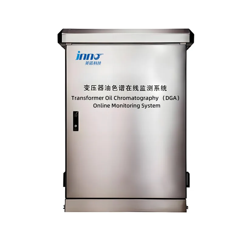
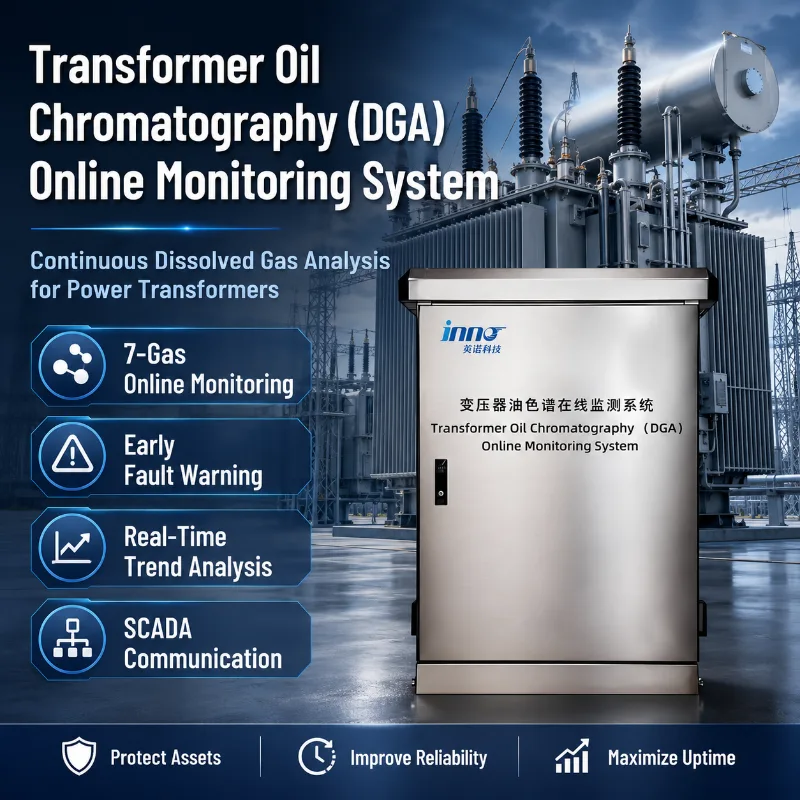
The INNOFZ online DGA system is delivered as an integrated, field-ready unit comprising three functional layers:
Front-End Oil Sampling and Gas Extraction Unit
The stainless-steel sampling module connects directly to the transformer's upper and lower oil valves, establishing a low-flow oil circulation loop. The dynamic vacuum degassing membrane extracts dissolved gases from the circulating oil stream continuously, transferring them to the analytical chamber without exposing the oil to atmosphere or introducing gas contamination.
Analytical Engine — Gas Chromatograph and Signal Processing
Extracted gases are injected into a packed GC column, separated by retention time, and quantified by thermal conductivity (TCD) and flame ionization (FID) detectors. Raw detector signals are digitized, temperature-compensated, and processed by the embedded controller, which applies calibration curves stored in non-volatile memory. All seven gas concentrations are computed and time-stamped within each analysis cycle.
Supervisory HMI, Data Management, and Communication
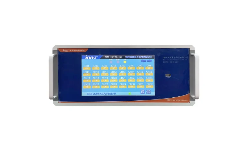
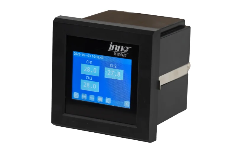
A local touch-panel HMI displays real-time gas concentration trends, alarm status, diagnostic conclusions (three-ratio, David triangle), and historical charts. All data is simultaneously transmitted upstream to the substation SCADA or asset management system via the configured communication protocol. Alarm set-points, calibration parameters, and reporting intervals are configurable through both the local HMI and remote interface.
Optional Accessories and Expansion Modules
- On-site high-purity nitrogen generator (eliminates bottled carrier-gas logistics)
- Integrated moisture-in-oil sensor for comprehensive insulation condition assessment
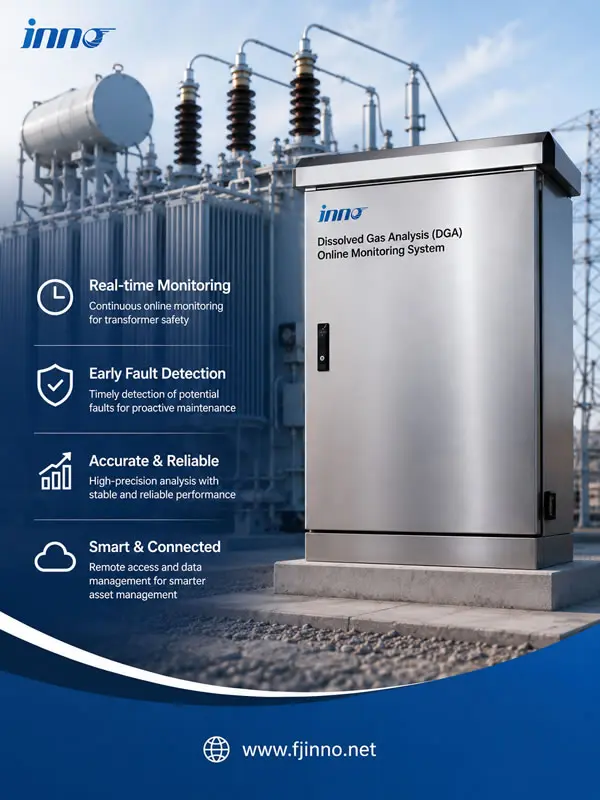
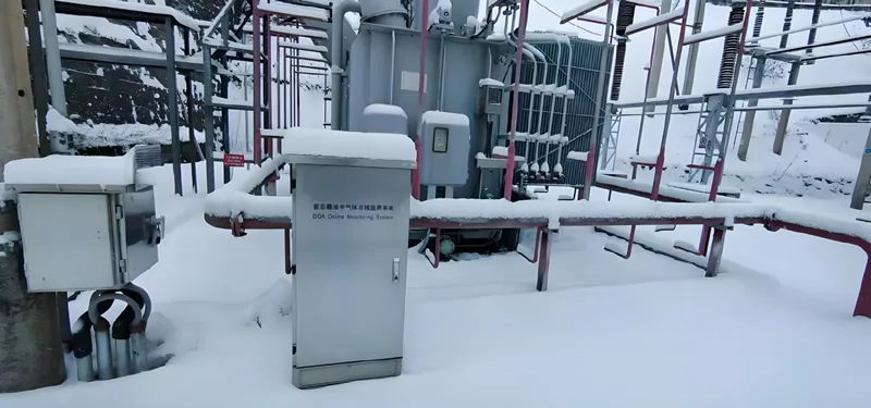
- Outdoor weatherproof cabinet with thermostat-controlled ventilation
- Remote monitoring display panel for control-room installation
How Online Dissolved Gas Analysis Works — Step by Step
-
Continuous Oil Circulation from Live Transformer
A small-displacement gear pump draws insulating oil from the transformer's lower sampling valve and returns it to the upper valve, maintaining a low-flow loop that is thermally and chemically representative of the bulk oil without disturbing transformer operation.
-
Dynamic Vacuum Degassing — Dissolved Gas Extraction
The circulating oil stream passes across a semi-permeable membrane maintained under controlled vacuum. Dissolved gases migrate through the membrane driven by partial-pressure differential, accumulating in a sealed extraction chamber. The vacuum degassing method achieves high extraction efficiency with minimal oil consumption and no chemical reagents.
-
Gas Chromatographic Separation of the Seven Fault Gases
Extracted gas is injected as a discrete sample into the temperature-controlled GC column. Each molecular species migrates through the column at a characteristic velocity, emerging at separate, reproducible retention times that uniquely identify H₂, CH₄, C₂H₆, C₂H₄, C₂H₂, CO, and CO₂ even in complex mixtures.
-
Detector Quantification and Analog-to-Digital Conversion
As each gas exits the column, TCD and FID detectors generate proportional electrical signals. High-resolution A/D conversion captures peak areas, which are translated into gas concentrations in μL/L (ppm by volume) using stored multi-point calibration data.
-
Automated Fault Interpretation and Trend Analysis
Computed concentrations are compared against configured alarm thresholds and fed into onboard interpretation algorithms. The system outputs the current fault classification (thermal fault, partial discharge, arcing, cellulose degradation, or normal), rate-of-gas-increase, and historical trend plots — automatically, every cycle.
-
Data Transmission to SCADA and Long-Term Storage
All results, alarm events, and diagnostic conclusions are logged locally and transmitted upstream via MODBUS or IEC 61850 within seconds of the analysis completing. Remote operators receive the same quality of information as engineers standing at the HMI.
Applications — Where Online DGA Monitoring Delivers the Greatest Value
Utility Substation Power Transformers
High-voltage transmission and grid substation transformers represent assets where unexpected failure triggers widespread outages and replacement costs exceeding millions of dollars. Continuous online DGA monitoring enables utilities to transition from time-based maintenance schedules to condition-based maintenance (CBM), intervening only when dissolved gas trends indicate genuine fault development.
Industrial Plant Distribution and Generator Step-Up Transformers
Process industries — petrochemical, steel, mining, and semiconductor fabrication — depend on uninterrupted power supply to production lines where a single unplanned outage can cost far more than the transformer itself. Online DGA provides the early-warning lead time that allows planned removal and replacement during scheduled plant shutdowns.
Aging Transformer Fleet Management
As the average age of installed transformer fleets rises globally, dissolved gas analysis becomes an increasingly important tool for extending service life responsibly. Continuous DGA data supports end-of-life assessment, load-management decisions, and capital expenditure planning by replacing calendar-based assumptions with real asset condition data.
Remote and Unmanned Substations
Where on-site inspection is infrequent by design, online DGA with SCADA integration ensures that the substation effectively monitors itself. Alarm events are pushed to operators immediately, compressing the response window that in an unmonitored site could otherwise extend to weeks between sampling rounds.
Dissolved Gas Analysis Standards, Compliance, and Interpretation Frameworks
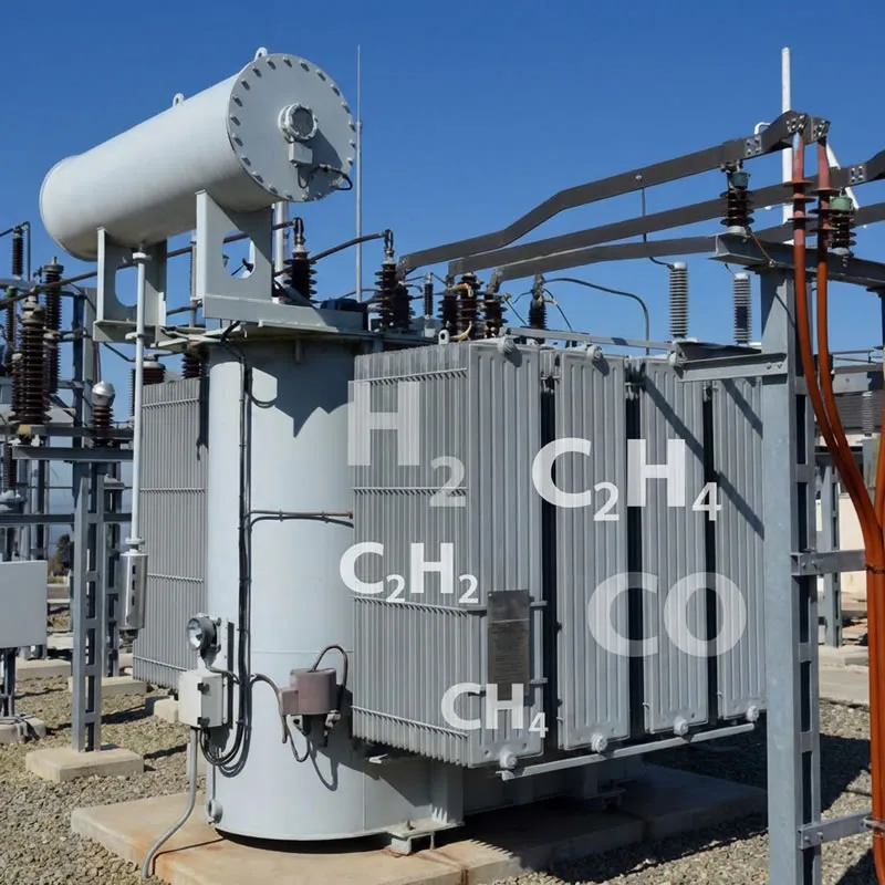
The INNOFZ online DGA system is designed and validated against the leading international standards governing transformer oil dissolved gas analysis testing, gas extraction methodology, and fault interpretation.
IEC 60567 — Oil-Filled Electrical Equipment Gas Extraction Methods
IEC 60567 defines the reference procedures for extracting dissolved gases from insulating oil, including vacuum extraction, stripping, and headspace methods. The INNOFZ dynamic vacuum membrane degassing design conforms to the extraction principles established in this standard, ensuring that results are comparable with laboratory reference measurements and inter-laboratory calibration data.
IEEE C57.104 — Guide for the Interpretation of Gases in Transformer Oil
The IEEE C57.104 guide establishes concentration thresholds and rate-of-increase limits for each key fault gas, along with the condition codes (Condition 1 through 4) used widely by North American utilities. INNOFZ embeds these thresholds as configurable alarm set-points, and the onboard interpretation engine applies the C57.104 key gas method alongside other diagnostic approaches.
IEC 60599 — Interpretation of Dissolved and Free Gas Analysis
IEC 60599 provides the international consensus framework for ratio-based fault diagnosis, including the three-ratio (Rogers ratio) method that classifies faults into thermal, partial discharge, and electrical discharge categories. The automated diagnostic engine in the INNOFZ system implements IEC 60599 ratio calculations on every analysis cycle.
IEC 61850 — Substation Communication Standard
Full native IEC 61850 MMS and GOOSE support means the DGA monitor integrates as a logical node within IEC 61850-based digital substation architectures without requiring proprietary middleware or protocol conversion gateways.
DL/T 722 — Chinese National Standard for Transformer DGA
For projects in markets that adopt DL/T 722 as the governing dissolved gas analysis standard, INNOFZ supports DL/T 722 threshold tables and diagnostic criteria as an alternative or parallel interpretation profile, selectable via system configuration.
Frequently Asked Questions — Transformer Dissolved Gas Analysis
Qu'est-ce que l'analyse des gaz dissous (DGA) dans l'huile de transformateur ?
Dissolved gas analysis is a diagnostic technique that identifies and quantifies gases dissolved in transformer insulating oil. Internal faults — including overheating of the oil or cellulose insulation, partial discharge, and electrical arcing — each produce a characteristic mix of hydrocarbon and non-hydrocarbon gases at rates correlated with fault severity. By analyzing the types and concentrations of these dissolved gases, engineers can determine what kind of fault is developing, how serious it is, and how quickly it is progressing, without taking the transformer out of service.
What is the difference between online and offline DGA monitoring for transformers?
Offline DGA requires a technician to collect an oil sample, transport it to a laboratory, and wait for analysis — a process that typically takes from one day to several weeks. Faults that develop rapidly during that interval go undetected until the next sampling round. Online DGA monitoring performs the entire extraction and gas chromatographic analysis automatically at the installation site on a continuous cycle, delivering results every one to two hours without any manual intervention. This eliminates blind intervals and enables alarm-driven response to fast-developing faults such as arc discharge, which can progress from detectable to catastrophic within hours.
What gases does a DGA system monitor in transformer oil, and why?
A standard DGA system monitors seven fault gases: hydrogen (H₂), methane (CH₄), ethane (C₂H₆), ethylene (C₂H₄), acetylene (C₂H₂), carbon monoxide (CO), and carbon dioxide (CO₂). Each gas, or combination of gases, is associated with specific fault mechanisms. Acetylene is strongly associated with high-energy electrical arcing because it requires temperatures above 1,000 °C to form. Ethylene and ethane indicate thermal faults at progressively lower temperatures. Carbon monoxide and CO₂ are produced by cellulose (paper insulation) degradation, and hydrogen is the primary marker for partial discharge. Monitoring all seven gases together allows ratio-based methods to distinguish between fault types with high specificity.
How often should transformer oil DGA be performed?
IEC 60599 and IEEE C57.104 both provide guidance on DGA sampling frequency based on transformer criticality and current fault status. For a transformer in normal condition (Condition 1 under C57.104), annual offline sampling is the minimum; for one showing elevated gas levels, monthly or quarterly sampling is recommended. Online DGA monitoring removes the sampling-frequency decision entirely — continuous measurement every one to two hours provides maximum sensitivity regardless of how rapidly a fault evolves, and is the preferred approach for critical transformers, aging assets, and unattended substations where rapid response to abnormal conditions is essential.
How do engineers interpret DGA test results using dissolved gas analysis standards?
Interpretation proceeds in layers. First, absolute gas concentrations are compared against the threshold tables in IEEE C57.104 or IEC 60599 to classify overall condition. Second, gas ratios — the three-ratio (Rogers ratio) method defined in IEC 60599, or the Doernenburg method — are calculated to identify fault type. Third, rate-of-gas increase over time is evaluated; a rapidly rising concentration demands more urgent attention than a static elevated level. The INNOFZ online DGA system automates all three interpretation layers continuously, presenting operators with both the raw concentration data and the derived fault classification on the same display, updated with every analysis cycle.
Can the INNOFZ DGA monitoring system be installed on an energized transformer?
Yes. The system connects to the transformer's existing oil sampling valves and does not require the transformer to be de-energized, drained, or taken out of service at any point during installation or commissioning. The oil circulation loop operates at low flow rates that have no measurable effect on transformer oil pressure or temperature. This live (hot-oil) installation capability makes the system practical for critical transformers where outage windows are limited or unavailable.