

قياس درجة الحرارة في ظروف الجهد العالي: الطرق وأجهزة الاستشعار
发布时间:6 سبتمبر 2026 الساعة 12:07:16
- High voltage temperature measurement requires a sensor and measurement method that can operate safely around strong electric fields, magnetic fields and large electrical potential differences.
- مستشعرات درجة الحرارة التي تعمل بالألياف الضوئية are particularly suitable for direct measurement inside transformers, generators and other high-voltage equipment because the sensing point can be electrically passive and immune to electromagnetic interference.
- RTDs and thermocouples remain widely used when electrical isolation, wiring and electromagnetic interference can be adequately controlled.
- Infrared thermal imaging is useful for non-contact surface temperature inspection, but it normally cannot directly measure inaccessible internal winding hot spots.
- The best high voltage temperature sensor depends on whether the measurement is internal or external, point or area based, permanent or temporary, and whether direct electrical isolation is required.
- For critical equipment, combining direct temperature sensing with thermal models, load information and condition monitoring can provide a more complete thermal picture than relying on one measurement alone.
High voltage temperature measurement is fundamentally different from ordinary industrial temperature measurement. The temperature itself may not be difficult to detect, but the electrical environment around the sensor can make conventional measurement methods difficult to install, isolate or maintain.
Transformer windings, generator windings, reactors, switchgear, busbars and high-voltage test equipment can operate in strong electromagnetic fields and at electrical potentials that make metallic sensors and conventional wiring unsuitable for certain measurement locations. Engineers therefore need to evaluate not only temperature range and accuracy, but also electrical isolation, EMI immunity, sensor location, installation access and system integration.
This guide compares the main methods used for temperature measurement in high-voltage equipment and explains when fiber optic temperature monitoring, electrical contact sensors, infrared measurement or calculated thermal monitoring should be considered.
Table of Contents
- 1. What Is High Voltage Temperature Measurement?
- 2. Why Is Temperature Measurement Difficult in High-Voltage Equipment?
- 3. High Voltage Temperature Measurement Methods
- 4. High Voltage Temperature Sensor Comparison
- 5. Fiber Optic Temperature Sensors for High Voltage Measurement
- 6. High Voltage Temperature Measurement Applications
- 7. High Voltage Temperature Sensor Selection
- 8. Sensor Placement and Installation
- 9. Standards and Published Engineering Evidence
- 10. High Voltage Temperature Monitoring System Architecture
- 11. Example High Voltage Temperature Monitoring Configurations
- 12. Common High Voltage Temperature Measurement Mistakes
- 13. Frequently Asked Questions
- 14. Conclusion
1. What Is High Voltage Temperature Measurement?
1.1 High Voltage Temperature Measurement Definition
High voltage temperature measurement refers to measuring temperature on or inside electrical equipment where high electrical potential, strong electric fields, magnetic fields or switching disturbances influence sensor selection and installation.
The objective may be as simple as checking the temperature of an external connection or as demanding as measuring the temperature of a conductor embedded inside an energized transformer winding.
These two situations require very different temperature measurement technologies.
1.2 What Temperatures Are Measured in High-Voltage Equipment?
Typical measurement targets include:
- Transformer winding hot spots
- درجة حرارة زيت المحول
- Generator and motor winding temperature
- Busbar and electrical connection temperature
- Switchgear contact and cable termination temperature
- Reactor winding temperature
- Power electronic module temperature
- High-voltage laboratory test-object temperature
- Cooling-system inlet and outlet temperature
The correct sensor depends heavily on whether the temperature of interest exists on an accessible surface or deep inside the equipment.
1.3 Direct vs Indirect High Voltage Temperature Measurement
A direct temperature measurement places a sensing element at or very close to the physical location of interest. An embedded winding sensor is a good example.
An indirect method estimates or infers thermal condition from another parameter. For example, transformer winding hot-spot temperature can be estimated using load, oil temperature and a thermal model.
Both approaches can be valuable. Direct sensing provides temperature at the actual sensor location, while thermal models can continuously estimate conditions at locations where installing a sensor is impractical.
2. Why Is Temperature Measurement Difficult in High-Voltage Equipment?
2.1 Electrical Isolation in High Voltage Temperature Measurement
A conventional RTD or thermocouple contains conductive materials and requires electrical wiring. When the sensing point is located near a high-potential conductor, the complete measurement circuit must be designed so that the sensor, cable, signal conditioner and data-acquisition equipment maintain appropriate electrical isolation.
This does not mean RTDs or thermocouples cannot be used in high-voltage equipment. They are widely used in suitable locations. The important question is whether a metallic sensing element and electrical lead wires are compatible with the specific measurement location.
2.2 Electromagnetic Interference and Temperature Sensors
Transformers, generators, converters and high-current conductors can create strong electromagnetic fields. Switching equipment and power electronics can introduce additional electrical noise.
Electrical temperature signals can therefore require shielding, grounding, isolation and careful cable routing.
و EMI-immune temperature sensor based on optical transmission can avoid many of these signal-interference problems because the temperature information is transmitted through optical fiber rather than a conventional electrical measurement circuit.
2.3 Internal High Voltage Temperature Measurement
Some of the most valuable temperatures are also the hardest to access.
A transformer winding hot spot, for example, may be located inside insulation and winding structures that become inaccessible after manufacturing. Surface infrared inspection cannot see through the transformer tank and oil to measure this internal location.
For this reason, direct internal monitoring normally has to be planned during equipment design or manufacturing. Embedded fiber optic temperature sensors for transformer windings are one option for this type of measurement.
3. High Voltage Temperature Measurement Methods
3.1 Fiber Optic Temperature Measurement
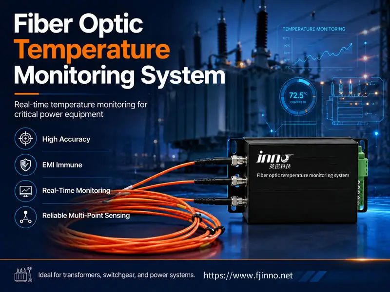
Fiber optic temperature measurement uses optical signals instead of electrical signals at the sensing point. Depending on the sensing technology, temperature can influence fluorescence lifetime, reflected wavelength, optical scattering or another optical property.
For high-voltage point measurements, fluorescence-based sensing is particularly useful because a small temperature probe can be installed at a selected location while the electronic interrogator remains away from the high-voltage sensing point.
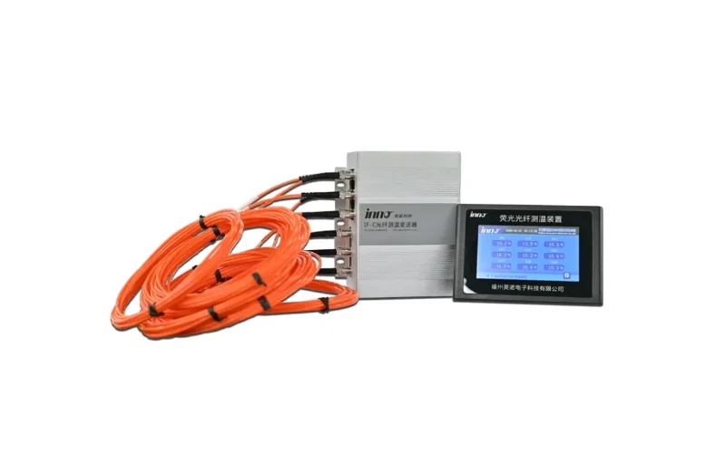
كامل multi-channel fiber optic temperature measurement system can collect multiple direct temperature points from one piece of equipment or several monitored zones.
3.2 RTD Temperature Measurement in High-Voltage Equipment
Resistance temperature detectors measure temperature through the predictable change in electrical resistance of a sensing material, commonly platinum.
RTDs are widely used because they can provide stable industrial temperature measurement. They are suitable for many transformer oil, enclosure, motor and process measurements where the sensor and wiring can be safely integrated.
However, when an RTD would have to be installed directly within a very high electrical potential region, electrical isolation and conductive wiring become important engineering considerations.
3.3 Thermocouple Temperature Measurement
Thermocouples measure temperature using a thermoelectric voltage generated by dissimilar conductors.
They are rugged, widely available and suitable for many industrial temperature ranges. They remain useful for laboratory testing, equipment surfaces and locations where electrical sensor installation is acceptable.
Like RTDs, however, thermocouples are electrically conductive. Signal integrity, grounding and isolation need to be considered when measurements are made close to high-voltage conductors.
3.4 Infrared and Thermal Imaging for High Voltage Equipment
Infrared thermography is one of the most useful non-contact methods for high-voltage inspection.
Typical targets include:
- Busbar joints
- Electrical terminals
- Switchgear connections
- البطانات
- Cable terminations
- Accessible transformer surfaces
The major advantage is that inspection can often be performed without physically attaching a sensor to the energized conductor.
The limitation is equally important: infrared systems primarily observe accessible surfaces. Results can also depend on emissivity, viewing angle, distance, reflections and environmental conditions.
Infrared inspection therefore complements rather than replaces embedded temperature sensing when the true thermal point is located inside the equipment.
3.5 Calculated and Model-Based Temperature Monitoring
Thermal models provide another method when direct measurement is unavailable.
In transformer applications, parameters such as load, ambient condition, oil temperature, winding gradients and cooling state can be used to estimate internal thermal conditions.
This approach forms an important part of مراقبة درجة حرارة المحول and can be combined with direct sensors to compare predicted and measured temperature behavior.
4. High Voltage Temperature Sensor Comparison
| Measurement Method | Contact / Non-Contact | Electrical Signal at Sensor | مقاومة التداخل الكهرومغناطيسي | Internal Measurement | Typical High Voltage Application |
|---|---|---|---|---|---|
| Fluorescence Fiber Optic Sensor | الاتصال | No conventional electrical signal at sensing point | Excellent | Suitable for embedded point measurement | Transformer and generator windings, high-voltage test equipment |
| FBG Fiber Optic Sensor | الاتصال | No conventional electrical signal at sensing point | Excellent | Suitable with appropriate sensor packaging | Multipoint temperature and structural sensing |
| RTD | الاتصال | نعم | يعتمد على التثبيت | Possible where electrical design permits | Oil, surface, enclosure and conventional industrial measurement |
| Thermocouple | الاتصال | نعم | يعتمد على التثبيت | Possible where electrical design permits | Testing and industrial temperature measurement |
| Infrared / Thermal Imaging | Non-contact | No contact sensor | Not based on electrical sensor signal | Normally surface only | Connections, busbars, terminals and accessible surfaces |
| النموذج الحراري | Calculated | No direct sensor required at calculated point | Not applicable to calculation itself | Estimated rather than directly measured | Transformer hot-spot and loading assessment |
The table shows why there is no single “best” high voltage temperature sensor. The correct method depends on what must actually be measured.
5. Fiber Optic Temperature Sensors for High Voltage Measurement
5.1 Why Fiber Optic Temperature Sensors Work in High-Voltage Environments
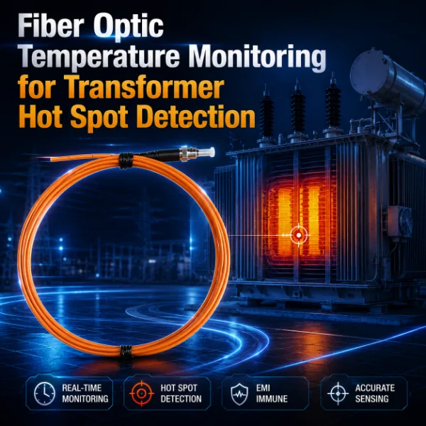
The main advantage of a fiber optic temperature sensor for high voltage is the separation between the optical sensing point and conventional electronic instrumentation.
The probe and fiber can be designed using dielectric materials, while optical signals carry measurement information to an interrogator positioned outside the critical high-voltage zone.
This gives fiber optic sensing several practical characteristics:
- Immunity to electromagnetic interference at the optical sensing path
- No conventional electrical measurement current at the sensing point
- Suitability for strong electric and magnetic fields
- Small sensing probes for embedded measurements
- Remote placement of electronic instrumentation
- Multi-channel point temperature monitoring
5.2 Fluorescence Fiber Optic Temperature Sensors
INNO's primary fiber optic temperature technology is fluorescence-based point sensing.
A fluorescent sensing material is located at the probe tip. It is optically excited, after which its fluorescence response decays. The decay lifetime changes with temperature, allowing the interrogator to convert the optical response into a temperature value.
This method measures a specific point and should not be confused with distributed temperature sensing.
For installations requiring individual probes, see the fluorescent fiber optic temperature sensor probes.
5.3 Point Fiber Optic Sensing vs Distributed Temperature Sensing
Point and distributed fiber optic temperature measurement solve different problems.
| Characteristic | Point Fiber Optic Sensor | DTS |
|---|---|---|
| Measurement Result | Temperature at selected sensor locations | Temperature profile along sensing fiber |
| Typical Distance | Specific local measurement points | Long distributed routes |
| تطبيق نموذجي | Transformer winding hot spots, generators, high-voltage components | Cables, tunnels, pipelines and long infrastructure |
| INNO Focus | Fluorescence-based point sensing | Not the primary technology discussed here |
For a transformer winding, knowing the temperature of several carefully selected hot-spot locations may be more useful than obtaining a long distributed temperature profile.
5.4 Multi-Channel Fiber Optic Temperature Measurement
High-voltage equipment often contains more than one thermally critical point.
A transformer may require multiple winding temperature probes. A generator may require monitoring across several stator slots or phases. A laboratory system may need simultaneous measurement at multiple isolated electrical potentials.
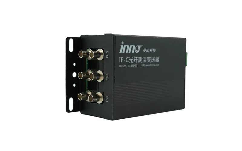
INNO provides systems ranging from compact sensing modules to higher-channel-count platforms, including a 3-channel fiber optic temperature transmitter and a 64-channel fluorescent fiber optic temperature measurement system.
The required channel count should be selected from the thermal measurement objective rather than simply maximizing the number of sensors.
6. High Voltage Temperature Measurement Applications
6.1 Transformer Winding High Voltage Temperature Measurement
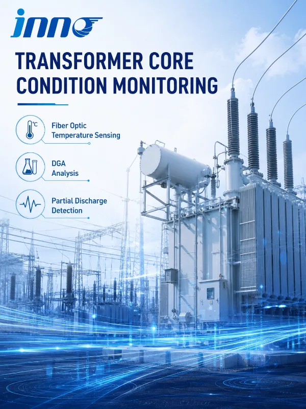
Transformer windings are one of the clearest examples of why optical temperature sensing is valuable.
The winding hot spot can exist inside the insulation structure at high electrical potential and in a strong electromagnetic environment. External surface measurement cannot directly observe this location.
Embedded fiber optic temperature sensors for transformer winding hot spot monitoring can measure temperature directly at selected internal points.
For complete application design, see transformer winding hot spot monitoring و oil-immersed transformer monitoring.
6.2 Oil-Immersed Transformer Temperature Measurement
An oil-immersed transformer contains several different thermal quantities that should not be treated as the same measurement:
- درجة الحرارة المحيطة
- Bottom oil temperature
- أقصى درجة حرارة للزيت
- Average winding temperature
- Calculated winding hot spot
- Direct winding temperature at embedded sensor locations
A fiber optic system can be used for direct winding measurements while conventional devices monitor oil and other transformer conditions.
For broader monitoring, the transformer oil temperature, level and pressure monitoring system can complement embedded winding sensing.
6.3 Dry-Type Transformer Temperature Measurement
Dry-type transformers also require temperature monitoring, but the monitoring architecture can differ substantially from liquid-immersed equipment.
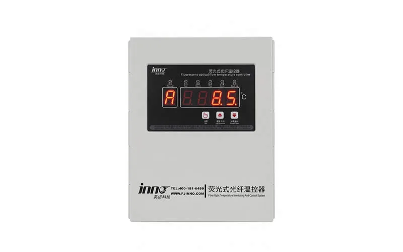
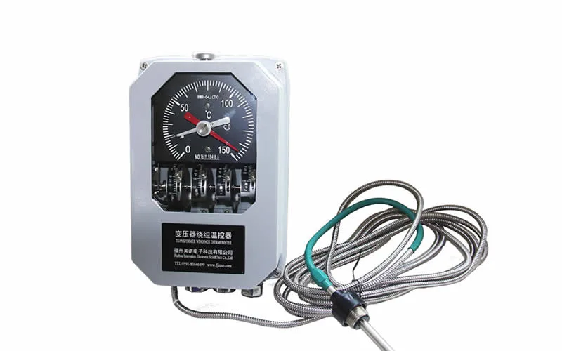
Conventional temperature controllers are widely used for winding temperature indication, fan control and alarms. INNO provides systems such as the IB-S201 dry-type transformer temperature monitor and controller.
Fiber optic measurement can also be considered when direct sensing is required in locations exposed to strong electromagnetic fields or electrical isolation constraints.
انظر dry-type transformer temperature monitoring for the application-level monitoring architecture.
6.4 Generator and Motor Winding Temperature Measurement
Large generators and motors combine high currents, strong magnetic fields and tightly packed winding structures. These characteristics make them another important application for electrically isolated sensing.
Fiber optic temperature probes can be positioned at selected winding locations during equipment manufacturing where direct embedded measurements are required.
This application is particularly relevant in power generation, where generator thermal condition can influence equipment loading and maintenance decisions.
6.5 Substation and High-Voltage Equipment Temperature Monitoring
Substations contain numerous thermally critical components, including transformers, switchgear, connections, busbars, cable terminations and other high-voltage assemblies.
No single sensor technology is ideal for all of them.
Infrared inspection may be effective for accessible surfaces, while permanent contact sensors may be better for enclosed or continuously monitored points. Embedded fiber optic sensing becomes valuable where the measurement must be electrically isolated or placed inside the high-voltage equipment.
See the broader substation monitoring application for system-level monitoring context.
6.6 High Voltage Testing and Laboratory Measurement
High-voltage laboratories frequently need temperature measurements while a test object is energized or exposed to strong electromagnetic fields.
A metallic sensor cable can influence the test setup, create unwanted electrical paths or introduce measurement noise depending on the experiment.
An optical sensor allows the temperature sensing element to remain isolated from the conventional electrical data-acquisition system, making fiber optic temperature measurement useful for dielectric testing, high-field experiments and electrically floating components.
7. High Voltage Temperature Sensor Selection
7.1 Select the Sensor by Measurement Location
The first question should not be “Which temperature sensor has the best specification?”
The first question should be:
Where is the temperature that actually needs to be measured?
For example:
- Accessible busbar surface → infrared or contact sensing may work.
- Transformer top oil → conventional oil temperature measurement may be appropriate.
- Internal transformer winding → embedded fiber optic sensing may be preferable.
- Long power cable route → distributed sensing may be more appropriate.
- Floating high-voltage test object → electrically passive optical sensing may simplify isolation.
7.2 Evaluate Electrical Potential and EMI
If the sensing location is electrically close to ground potential and EMI is manageable, a conventional industrial sensor may be completely appropriate.
If the sensing point is located directly within a high-voltage winding or electrically floating structure, a dielectric high voltage temperature sensor becomes much more attractive.
7.3 Determine Point vs Multi-Point Measurement
A single-channel measurement system is sufficient when only one critical point requires monitoring. INNO provides a single-channel fiber optic temperature sensing module for compact point-measurement configurations.
Equipment containing multiple phases, windings or thermal zones may require a multi-channel system.
Sensor count should be based on:
- Number of thermally critical zones
- Phase arrangement
- Required redundancy
- Expected hot-spot movement
- Thermal model results
- Monitoring objective
7.4 Check Temperature Range, Accuracy and Response Requirements
Temperature range alone should not determine sensor selection.
Engineering requirements should include:
- Required operating temperature range
- Measurement uncertainty or accuracy target
- Required repeatability
- Response-time requirement
- Long-term calibration stability
- Sensor dimensions
- طول الألياف
- Mechanical protection
- Environmental compatibility
Exact values should be confirmed using the datasheet of the selected sensor and interrogator configuration.
7.5 Check Communication and Control Requirements
Temperature measurement frequently needs to connect to a larger monitoring or control system.
Depending on the selected INNO model and configuration, integration can involve industrial interfaces such as RS485, Modbus, analog signals or relay outputs.
A fluorescent fiber optic temperature monitoring and control system can combine temperature acquisition with monitoring and control functions where required.
8. High Voltage Temperature Sensor Placement and Installation
8.1 Sensor Position Can Matter More Than Sensor Accuracy
A highly accurate sensor in the wrong location can provide less useful information than a slightly less accurate sensor positioned at the true thermal point of interest.
This is particularly important in windings because temperature is not uniformly distributed.
An optical sensor records the temperature at its own physical location. It cannot automatically determine whether an uninstrumented location elsewhere in the winding is hotter.
8.2 Use Thermal Analysis to Select Measurement Points
For critical high-voltage equipment, probe placement can be supported by:
- Electromagnetic loss calculation
- Thermal network modeling
- Computational fluid dynamics
- Previous temperature-rise testing
- Winding design experience
- Known cooling-flow paths
This approach is more reliable than installing sensors at equal distances without considering the actual thermal design.
8.3 Protect Fiber Optic Sensors During Installation
The optical sensing principle may be immune to EMI, but the physical fiber still requires correct mechanical installation.
Installation checks should include:
- Minimum bending radius
- Protection from crushing
- Probe fixing method
- Fiber lead routing
- Connector cleanliness
- Insulation compatibility
- Channel identification
- Continuity verification before final assembly
For mechanically demanding transformer installations, an armored fiber optic temperature sensor for oil-immersed transformer windings can be considered.
9. High Voltage Temperature Measurement Standards and Engineering Evidence
9.1 IEEE C57.165-2024 Temperature Measurement Guide
IEEE C57.165-2024, Guide for Temperature Measurements for Liquid-Immersed Transformers and Reactors, specifically addresses temperature measurement in liquid-immersed transformers and reactors.
The guide recognizes winding temperature as central to transformer thermal performance and discusses temperature measurement for windings and other transformer structures.
This is important for high-voltage temperature monitoring because it reinforces a basic engineering principle: reliable thermal control and analysis depend first on obtaining meaningful temperature information from the equipment.
9.2 IEC 60076-7 and Fiber Optic Transformer Temperature Measurement
IEC 60076-7:2018 is the loading guide for mineral-oil-immersed power transformers. It addresses operating temperatures, thermal aging and transformer thermal models.
The 2018 edition also includes guidance related to the number of fiber optic sensors used for temperature-rise testing, demonstrating that embedded optical temperature measurement is an established technique in transformer thermal evaluation.
9.3 IEEE C57.91-2025 Transformer Loading and Temperature
IEEE C57.91-2025 is the current IEEE guide for loading mineral-oil-immersed transformers and step-voltage regulators.
It addresses loading above nameplate rating, ambient conditions, cooling techniques, transformer temperature criteria and temperature calculation methods.
For online monitoring, this provides context for why load, cooling state and measured temperature should be evaluated together.
9.4 Published 20 MVA Transformer with 12 Fiber Optic Measurement Points
A published IEEE Sensors Journal study demonstrated a multipoint fiber optic sensing network integrated into a 20 MVA power transformer.
The system used 12 internal temperature sensing points distributed across locations including windings, cellulose insulation, the magnetic circuit and cooling-oil regions.
The significance of this example is not that every transformer needs 12 sensors. It demonstrates that multi-point optical temperature measurement has been physically integrated into large power transformer structures for continuous internal thermal monitoring.
9.5 Published 110 kV Transformer Fiber Optic Monitoring Example
Another published IEEE conference paper described fiber optic temperature monitoring applied to an 110 kV oil-immersed transformer.
The reported system operated for approximately 10 months, demonstrating direct internal optical temperature measurement under real transformer operating conditions.
This example used FBG rather than fluorescence sensing, but it remains useful evidence for the broader engineering feasibility of optical sensors inside high-voltage transformers.
9.6 A 20-Sensor Study Shows Why Probe Placement Matters
A 2023 IEEE Transactions on Instrumentation and Measurement study evaluated transformer thermal performance using 20 optical fiber sensors together with computational fluid dynamics.
The study found that a point temperature measurement does not necessarily represent the maximum critical temperature elsewhere in a transformer winding. Winding arrangement and oil-flow distribution influenced the thermal pattern and therefore the optimal sensor locations.
This supports an important rule for high voltage temperature measurement:
Sensor technology and sensor placement must be engineered together.
10. High Voltage Temperature Monitoring System Architecture
A typical permanent optical monitoring architecture can be represented as:
Temperature Probe → Optical Fiber → Fiber Optic Interrogator → Temperature Processing → Alarm Logic → PLC / SCADA / Monitoring Platform
10.1 High Voltage Temperature Sensor
The probe is installed at the temperature measurement location. Its construction depends on the application, insulation environment and required mechanical protection.
10.2 Optical Fiber and Extension Cable
The optical fiber transfers the sensing signal from the probe to the monitoring electronics.
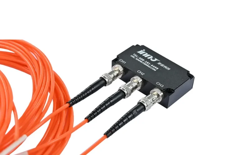
Where additional routing length or connection flexibility is required, a fiber optic temperature sensor extension cable can form part of the installation.
10.3 Fiber Optic Temperature Interrogator
The interrogator generates the optical excitation, detects the returned optical signal and calculates temperature.
Different applications can use compact modules such as the IF-G3 3-channel fiber optic temperature sensing module or larger multi-channel instruments.
10.4 Local Display and Remote Monitoring
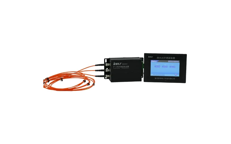
Where operators require local temperature indication, systems can include a fiber optic temperature measurement LCD display instrument.
For remote condition monitoring, the temperature values can be integrated into control systems or higher-level transformer monitoring platforms.
11. Example High Voltage Temperature Monitoring Configurations
11.1 Example: Three-Phase Transformer Winding Monitoring
Consider an illustrative three-phase transformer where both HV and LV windings are considered thermally important.
| Design Item | Illustrative Configuration |
|---|---|
| Phases | 3 |
| Monitored Windings per Phase | HV + LV |
| Temperature Points per Winding | 2 selected locations |
| Total Measurement Points | 3 × 2 × 2 = 12 |
| Measurement Method | Embedded point fiber optic sensing |
| Monitoring Objective | Compare phase, winding and hot-spot temperature trends |
This is an illustrative configuration, not a requirement. Actual sensor count should follow transformer thermal design and the monitoring objective.
11.2 Example: One Critical High Voltage Measurement Point
Some applications do not need a large monitoring system.
A laboratory test setup or electrically isolated component may require only one critical temperature point. In this case, a compact single-channel optical measurement module can be simpler and more economical than installing a large multi-channel platform.
11.3 Example: High Channel Count Temperature Monitoring
A research platform, large transformer, generator or industrial thermal test can require dozens of simultaneous temperature points.
A 64-channel platform allows the monitoring architecture to collect a much denser temperature map, but adding sensors is useful only when the additional measurement locations have a clear engineering purpose.
The objective should be better thermal information, not simply a higher channel count.
12. Common High Voltage Temperature Measurement Mistakes
12.1 Selecting a Sensor Only by Accuracy
Accuracy is important, but it is only one part of high-voltage sensor selection. Electrical isolation, EMI immunity, mechanical installation and actual probe location can have a greater effect on whether the measurement is useful.
12.2 Assuming Infrared Measurement Can See Internal Hot Spots
Thermal cameras are powerful diagnostic tools, but they generally measure accessible surfaces. A transformer tank surface temperature is not the same as the temperature of an internal winding conductor.
12.3 Assuming Fiber Optic Sensors Automatically Find the Hottest Point
A fiber optic sensor directly measures its installed location. It does not automatically find the true maximum temperature elsewhere in the equipment.
Thermal modeling and engineering knowledge should guide sensor placement.
12.4 Ignoring Mechanical Fiber Protection
EMI immunity does not mean mechanical immunity. Fibers can still be damaged by excessive bending, crushing, pulling or poor routing.
12.5 Using Too Few Temperature Points
A single measurement point may not represent a thermally complex three-phase system.
Where temperature distribution can vary significantly by phase, winding or cooling zone, multi-point monitoring should be considered.
12.6 Installing Too Many Sensors Without a Thermal Plan
The opposite problem also occurs. Installing dozens of probes without understanding likely hot spots can produce large amounts of data without improving diagnostic value.
Measurement points should be linked to identifiable thermal risks.
12.7 Treating Temperature as the Only Condition Indicator
Temperature is important, but high-voltage equipment can develop electrical, insulation and mechanical problems that are not fully represented by temperature alone.
For transformers, broader transformer monitoring may combine thermal information with dissolved gas analysis, partial discharge monitoring, bushing monitoring و مراقبة OLTC.
13. Frequently Asked Questions About High Voltage Temperature Measurement
13.1 What is high voltage temperature measurement?
High voltage temperature measurement is the measurement of temperature on or inside equipment operating in high electrical potential or strong electromagnetic environments. Sensor selection must therefore consider electrical isolation and EMI in addition to normal temperature specifications.
13.2 Which temperature sensor is best for high voltage equipment?
There is no universal best sensor. Fiber optic sensors are particularly suitable for direct electrically isolated measurements, RTDs and thermocouples remain useful in appropriate electrical locations, and infrared systems are effective for accessible surface inspections.
13.3 Why are fiber optic temperature sensors used in high-voltage equipment?
Fiber optic sensors transmit measurement information optically and can use electrically passive sensing probes. This makes them suitable for strong electromagnetic fields and locations where conventional electrical sensor wiring creates isolation challenges.
13.4 Are fiber optic temperature sensors immune to EMI?
The optical sensing and transmission path is inherently immune to electromagnetic interference because the measurement signal is carried by light rather than an electrical current. The complete monitoring system still requires correct installation and electronic equipment design.
13.5 Can fiber optic sensors measure transformer winding temperature directly?
Yes. A properly installed embedded fiber optic sensor measures temperature directly at its physical location in the transformer winding. See the dedicated fiber optic temperature measurement system for oil-immersed transformers.
13.6 Can infrared cameras measure transformer winding hot spots?
Normally not directly inside a closed oil-immersed transformer. Infrared systems observe accessible surface radiation, while the winding hot spot is located inside the transformer. Infrared inspection remains valuable for bushings, connections, terminals and external surfaces.
13.7 What is the difference between a fiber optic temperature sensor and an RTD?
A fiber optic sensor measures temperature using an optical response and transmits the measurement optically. An RTD measures the change in electrical resistance of a sensing element. Both can provide accurate temperature measurement, but their electrical characteristics and installation requirements are different.
13.8 How many fiber optic temperature sensors are required?
The quantity depends on equipment geometry, phases, winding design, predicted hot spots, required redundancy and monitoring objectives. There is no universal number that applies to every transformer or high-voltage system.
13.9 Can fiber optic temperature sensors connect to PLC or SCADA systems?
Yes, when the selected interrogator provides the required industrial communication interface. Depending on model and configuration, systems may provide RS485, Modbus, analog outputs, relay outputs or other integration options.
13.10 Is fiber optic temperature measurement the same as DTS?
No. Fluorescence-based fiber optic temperature sensing used for transformer and high-voltage hot-spot monitoring is typically a point measurement technology. DTS measures a distributed temperature profile along a length of sensing fiber.
13.11 Can high voltage temperature sensors be retrofitted?
It depends on the measurement location. External or accessible sensors may often be retrofitted. A sensor that must be embedded deep inside a transformer winding is usually easier to install during manufacturing or major refurbishment.
13.12 What data should be monitored together with high voltage temperature?
Depending on the equipment, useful supporting data can include load current, ambient temperature, cooling-system status, oil temperature, alarms and condition-monitoring parameters such as DGA or partial discharge. Combining these measurements provides better operating context than temperature alone.
14. Conclusion: High Voltage Temperature Measurement and Sensor Selection
High voltage temperature measurement requires more than choosing a sensor with the correct temperature range. Engineers must consider electrical potential, electromagnetic interference, measurement location, sensor installation, mechanical protection and monitoring-system architecture.
RTDs and thermocouples remain effective conventional temperature sensors where electrical wiring can be safely integrated. Infrared thermography provides valuable non-contact inspection of accessible high-voltage surfaces. Thermal models provide estimated internal temperatures when direct sensing is unavailable.
For direct temperature measurement inside high-voltage, strong electromagnetic or electrically isolated environments, مستشعرات درجة الحرارة التي تعمل بالألياف الضوئية provide an important alternative. Fluorescence-based point sensing is particularly suitable when temperature must be measured at selected transformer winding, generator winding or high-voltage equipment hot spots.
Published transformer studies using 12 internal optical sensing points in a 20 MVA transformer, optical sensing in a 110 kV transformer, and experiments using 20 optical probes combined with CFD analysis also demonstrate why both optical sensing technology and probe positioning matter in real thermal measurement systems.
For system selection, explore INNO's fiber optic temperature monitoring solutions, multi-channel fiber optic temperature measurement systems و power transformer monitoring applications.
Related High Voltage Temperature Measurement Resources
- مراقبة درجة الحرارة باستخدام الألياف الضوئية
- مراقبة درجة حرارة المحولات
- مراقبة النقاط الساخنة في لفات المحولات
- مستشعر درجة الحرارة من ألياف البوليميد الضوئية لملفات المحولات
- مستشعر درجة الحرارة المُدرع ذو الألياف الضوئية لملفات المحولات المغمورة بالزيت
- مستشعر درجة الحرارة بالألياف الضوئية لمراقبة النقاط الساخنة في لفات المحولات
- نظام قياس ومراقبة درجة الحرارة متعدد القنوات باستخدام الألياف الضوئية
- مراقبة محولات الطاقة
Technical References
- IEEE C57.165-2024 — IEEE Guide for Temperature Measurements for Liquid-Immersed Transformers and Reactors.
- IEC 60076-7:2018 — Power Transformers – Part 7: Loading Guide for Mineral-Oil-Immersed Power Transformers.
- IEEE C57.91-2025 — IEEE Guide for Loading Mineral-Oil-Immersed Transformers and Step-Voltage Regulators.
- IEEE Sensors Journal, 2008 — Multipoint Fiber-Optic Hot-Spot Sensing Network Integrated Into High Power Transformer for Continuous Monitoring.
- China International Conference on Electricity Distribution, 2014 — Online hot-spot temperature monitoring using optical fiber sensing in a 110 kV oil-immersed transformer.
- IEEE Transactions on Instrumentation and Measurement, 2023 — Evaluation of power transformer thermal performance and optical sensor positioning using CFD simulations and temperature-rise testing.







