
What Is the IF-TF Fiber Optic Temperature Measurement System?
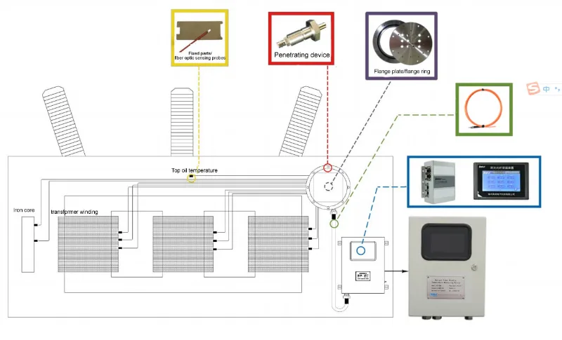
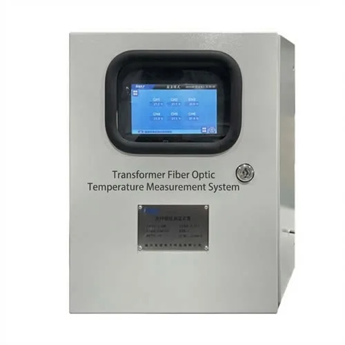
The IF-TF series is a complete نظام قياس درجة الحرارة بالألياف الضوئية designed for direct winding hot spot monitoring in oil-immersed power transformers. The system replaces indirect oil temperature estimation with real-time, contact measurement at the actual winding location — giving protection relays and cooling control systems accurate thermal data they can act on.
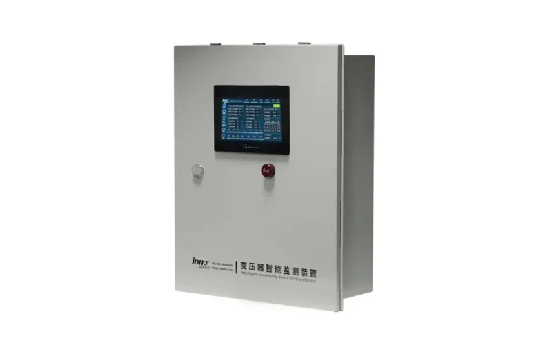
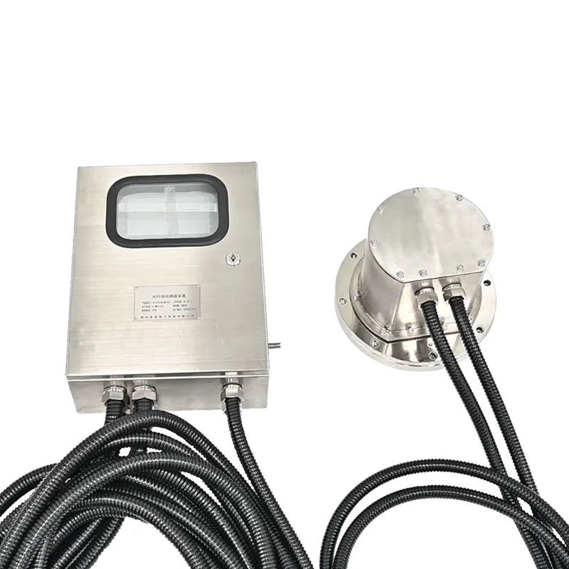
Every component is engineered for the high-voltage, oil-immersed environment: all-dielectric fiber optic probes rated to 100 KV, oil-resistant probe construction, 316 stainless steel flanges and penetrators rated to 150 KPa, and a stainless steel wall-mount transmitter enclosure rated IP55. The system ships as a matched assembly — probe, internal fiber, penetrator, flange, extension cable, and transmitter — configured to your transformer's channel count and fiber length requirements.
System Technical Specifications
| المعلمة | المواصفات |
|---|---|
| مصدر الطاقة | تيار متردد/تيار مستمر 220 فولت |
| نطاق درجات الحرارة | −40°C to +260°C (higher range customizable) |
| دقة القياس | ±1°C (higher accuracy customizable) |
| القرار | 0.1 درجة مئوية |
| عدد القنوات | 1–18 (customizable) |
| Communication Output | RS485 / Modbus-RTU; 4–20 mA analog current output |
| Sensing Fiber Type | Quartz fiber optic (fluorescent) |
| Fiber Optic Probe Length | 0–20 m customizable |
| Probe High Voltage Resistance | 100 كيلوفولت |
| قطر المسبار | 2.5 mm (smaller sizes customizable) |
| Probe Construction | Oil-resistant, fully non-metallic sensing tip |
| Transmitter Enclosure | 304 / 316 stainless steel, wall-mount, IP55 |
| Transmitter Dimensions | 460 × 150 × 380 mm |
| Flange / Penetrator Material | 316 stainless steel |
| Penetrator Pressure Rating | 150 KPa |
| Penetrator Thread | M14 × 1.0, fluorine rubber O-ring seal |
| الشهادات | CE, RoHS, ISO 9001 | UL, IECEx, ATEX, CSA, TÜV (customizable) |
مكونات النظام
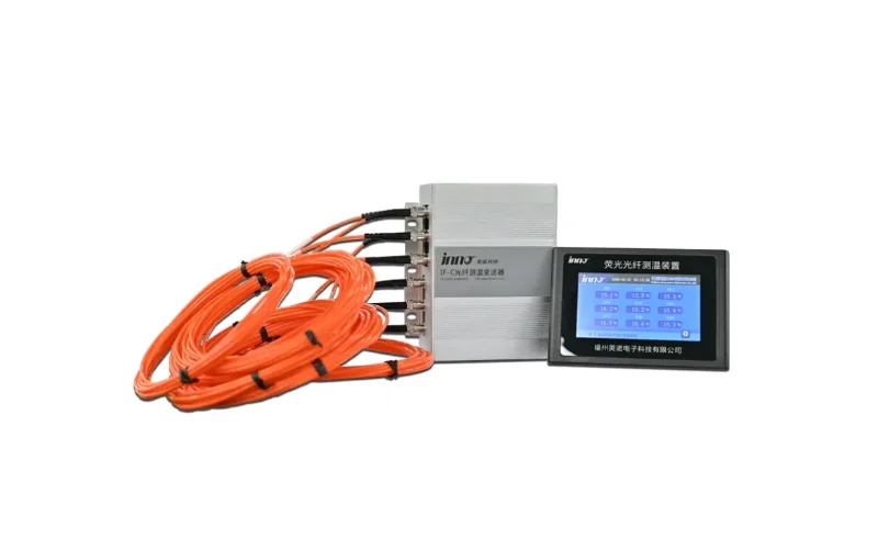
IF-TF Transmitter Unit
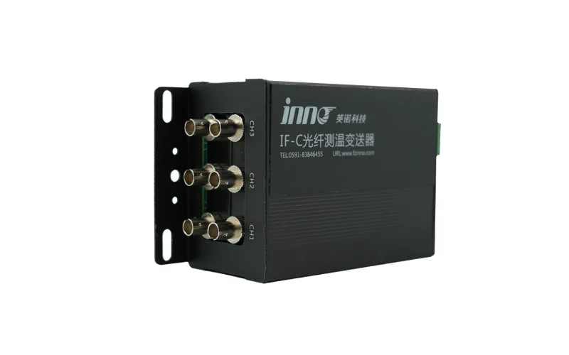
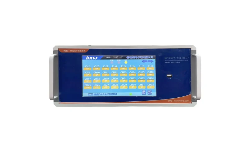
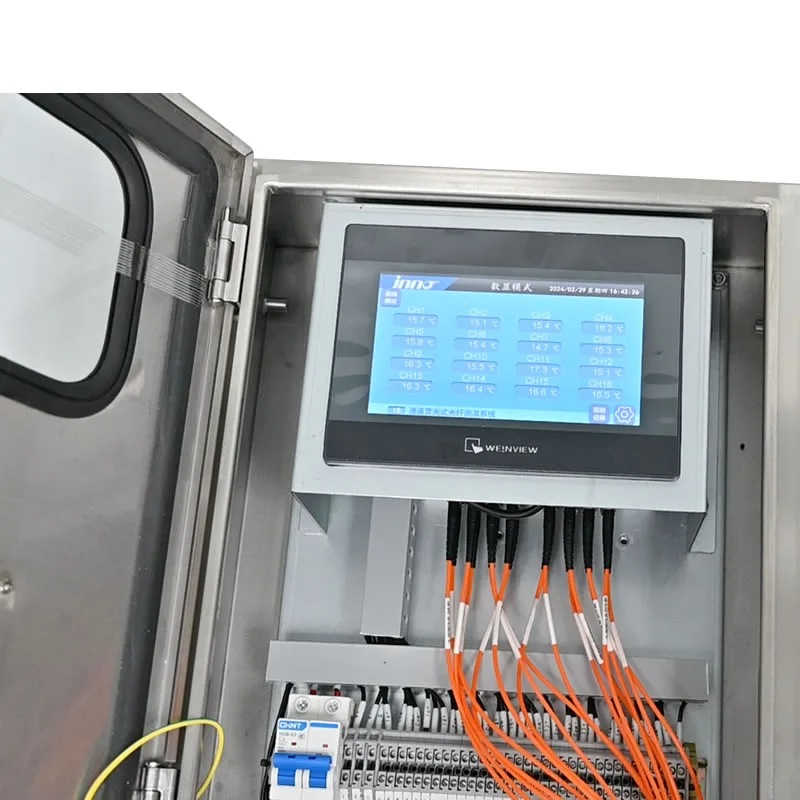
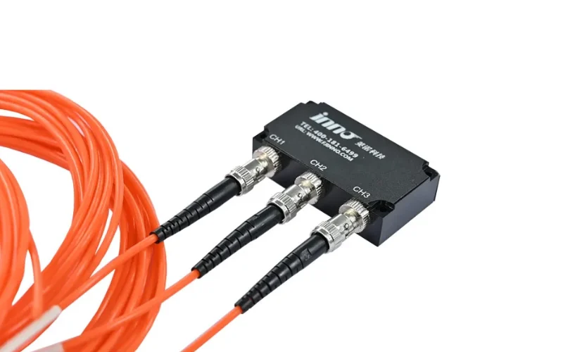
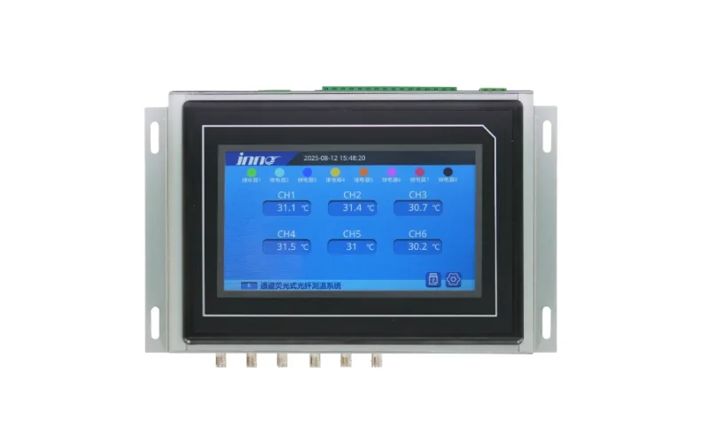
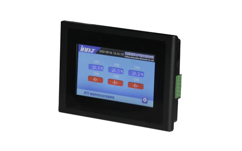
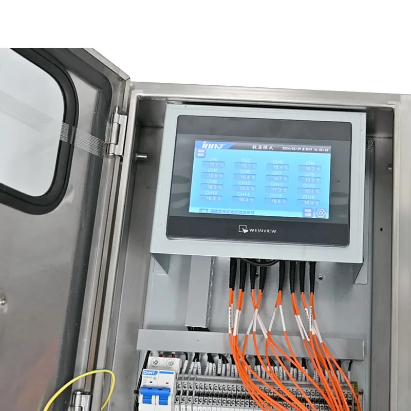
The transmitter is the signal processing core of the system. It generates excitation light pulses, receives fluorescence return signals from each probe channel, calculates temperature from the fluorescence decay time, and outputs readings via RS485 / Modbus-RTU and 4–20 mA analog. The front panel LCD displays live channel readings. Relay outputs for fan start, alarm, and trip are configurable per channel. The unit mounts in a 304 or 316 stainless steel three-proof enclosure rated IP55, suitable for outdoor substation installation directly on the transformer body or adjacent control cabinet.
Internal Fiber Optic Sensing Probe
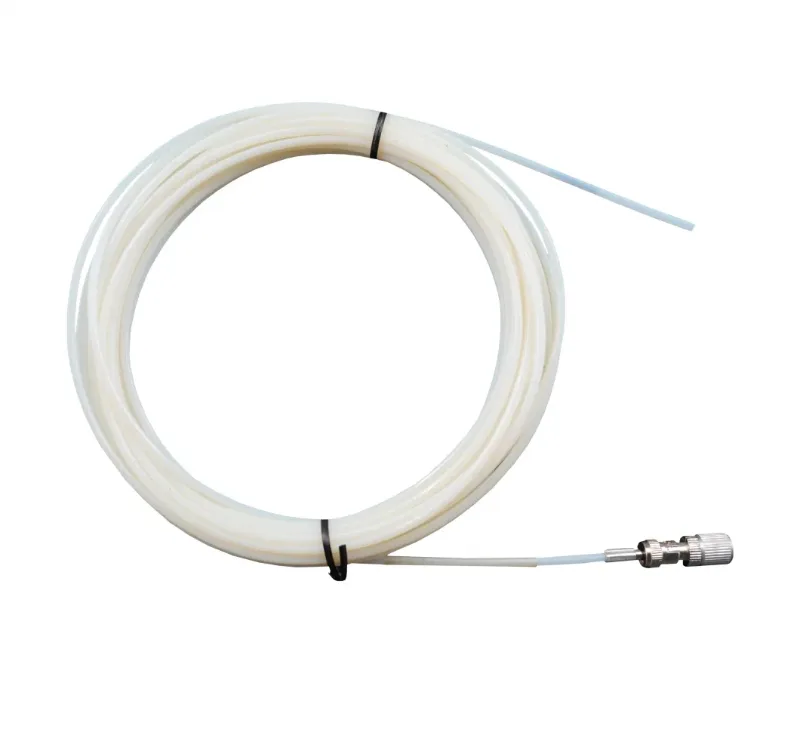
The sensing probe is inserted directly into the transformer winding during assembly or major overhaul. The sensing tip contains rare earth fluorescent material in a fully non-metallic housing — no metal conductors at any point from tip to transmitter. Rated to 100 KV, oil-resistant, 2.5 mm diameter. The probe tip contacts the winding conductor or insulation paper at the location of peak expected temperature. For a three-phase transformer, a minimum of three probes are placed — one per phase at the top of the high-voltage winding.
Fiber Optic Penetrator
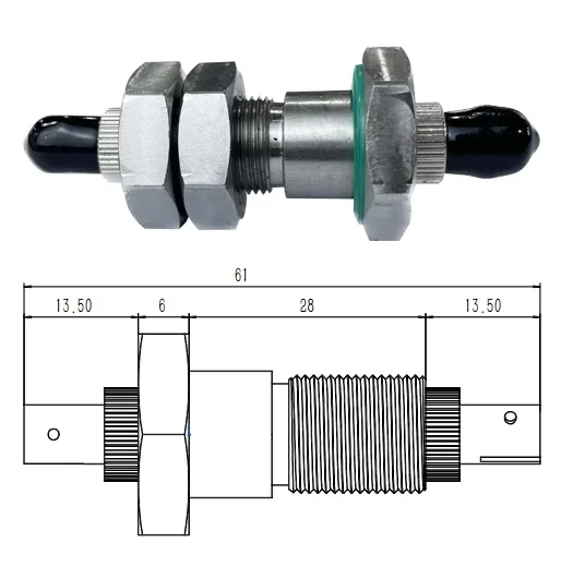
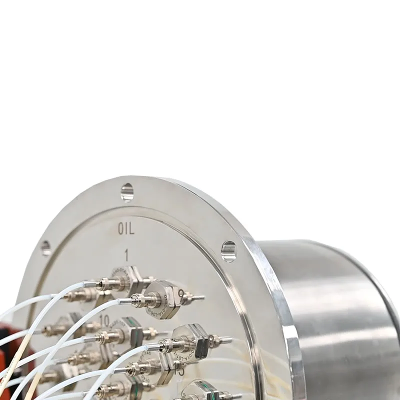
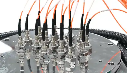
The penetrator provides the oil-tight transition between the internal probe fiber and the external extension cable. It threads through the transformer tank wall using M14 × 1.0 external thread and is sealed with a fluorine rubber O-ring rated to 150 KPa oil pressure. The 316 stainless steel body withstands long-term immersion in transformer oil without corrosion. The penetrator includes the body, O-ring, and M14 double nuts — fully proven installation hardware for oil-immersed transformer tank wall penetrations.
Flange Assembly
 |
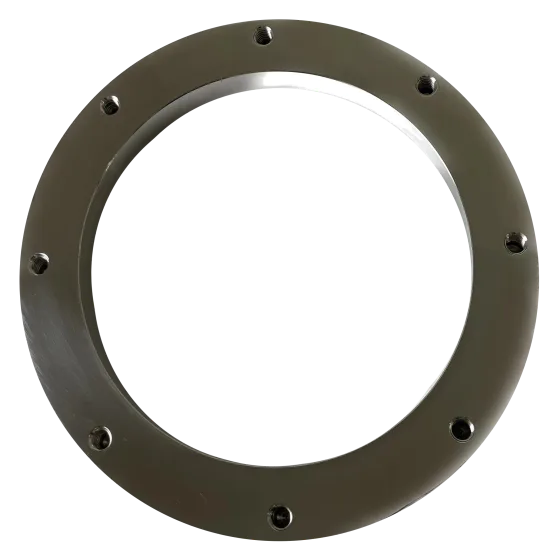 |
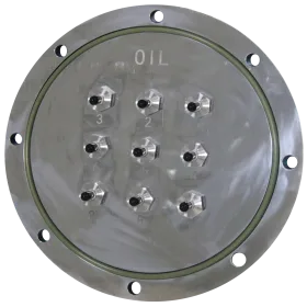
The flange ring is welded to the inner wall of the transformer tank. The flange plate mounts on the tank exterior, clamping the penetrators in position and providing a sealed, organized exit point for multiple fiber channels. Standard flange diameter is 305 mm in 316 stainless steel, supporting 1 to 16 penetrators. Dimensions are customizable per project. The flange system eliminates improvised, leak-prone penetration methods and provides a repeatable, maintainable installation standard.
Protective Cover
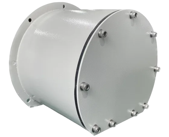
The protective cover installs over the flange on the exterior tank wall, protecting the penetrators and external fiber cable connections from mechanical damage and weather. Made from 304 stainless steel with an internal sealing gasket rated IP55. Bottom outlet holes (3 × Ø28 mm) accept PG21 waterproof cable glands for the external fiber extension cables running to the transmitter. Enclosure color is customizable for site identification requirements.
External Fiber Optic Extension Cable
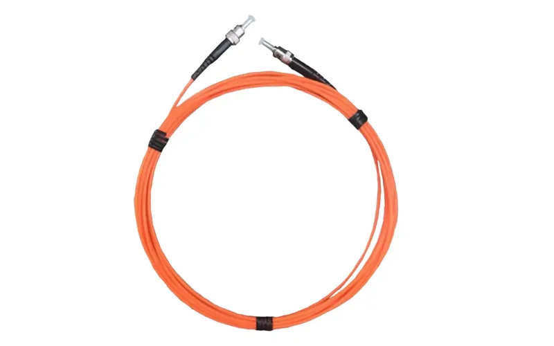
PTFE-jacketed quartz fiber extension cables run from the protective cover to the transmitter ST input ports. Standard lengths from 1 m to 20 m, custom lengths available. ST connectors on both ends. Rated −40°C to +260°C, 100 KV insulation, resistant to transformer oil, UV, and industrial chemicals. See the كابل تمديد لمستشعر درجة الحرارة بالألياف الضوئية product page for full specifications.
Why Direct Winding Temperature Measurement Matters
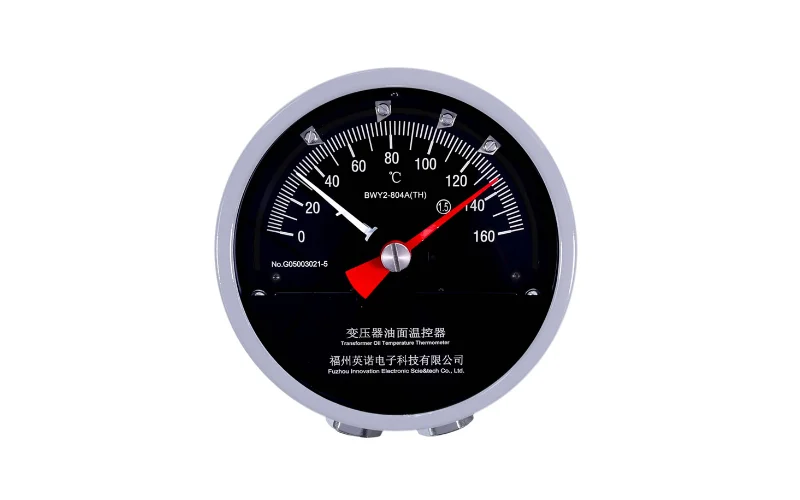
A transformer's top oil thermometer tells you the bulk oil temperature at the tank surface — not the temperature inside the winding where thermal degradation actually occurs. The winding hot spot, typically located near the top of the high-voltage coil, routinely runs 20°C to 40°C above the measured oil temperature under normal load. Under overload conditions, this gap widens further.
It is the hot spot temperature that determines insulation aging rate. Every 6°C increase above the rated hot spot temperature approximately doubles the rate of insulation degradation, per Arrhenius thermal aging models used in IEC 60076-7. A transformer running at an unknown 20°C hot spot excess for extended periods loses years of service life without any indication from its oil thermometer.
The IF-TF system closes this measurement gap. With probes placed directly at winding hot spot locations, the protection system operates on actual thermal data — enabling tighter cooling control, more accurate loss-of-life calculations, and earlier detection of developing thermal faults.
Key Performance Advantages
Complete EMI/RFI Immunity
Transformer windings generate intense electromagnetic fields during operation and switching. Conventional electronic temperature sensors mounted near winding conductors suffer from induced measurement errors, signal noise, and long-term component degradation from electromagnetic stress. Fiber optic temperature probes immune to EMI/RFI eliminate this problem entirely — the quartz fiber carries only light, with zero susceptibility to electric or magnetic field interference at any frequency. Readings are stable and accurate regardless of transformer loading, switching operations, or adjacent equipment.
100 KV Electrical Isolation
The all-dielectric fiber optic assembly creates complete galvanic isolation between the high-voltage winding and the transmitter at ground potential. There is no conductive path through the measurement system. This is the fundamental reason why fiber optic sensing is the only technology suitable for direct winding contact measurement in high-voltage transformers — and why it has become the standard method for مراقبة النقاط الساخنة في المحولات in modern power systems.
Real-Time Online Monitoring
The system provides continuous, real-time temperature data on all channels simultaneously. There is no polling delay, no averaging interval, and no sample-and-hold limitation. For أنظمة مراقبة المحولات عبر الإنترنت integrated with SCADA or protection relays, the Modbus-RTU register map provides instant access to all channel readings, alarm status, and relay output states. The 4–20 mA analog output option allows direct connection to legacy DCS or protection relay analog inputs without a Modbus interface.
Sealed, Maintainable Installation Architecture
The penetrator-flange-protective cover assembly provides a repeatable, leak-tested installation standard that can be inspected and serviced without opening the transformer. External fiber cables and transmitter connections are accessible from outside the tank. If an extension cable is damaged, it can be replaced without a transformer outage. The flange plate supports up to 16 penetrators in a single assembly, keeping the tank wall modification to a single sealed location.
Transformer Condition Monitoring Integration
Winding hot spot temperature is the primary thermal parameter in a comprehensive مراقبة حالة المحولات الكهربائية program. The IF-TF system's Modbus-RTU output integrates directly with transformer monitoring platforms, substation automation systems, and utility SCADA infrastructure.
Trending the winding temperature data over time provides early indicators of developing problems. Rising temperature at constant load points to cooling system degradation. Increasing phase-to-phase temperature asymmetry may indicate unbalanced loading or internal fault development. Combined with oil temperature, load current, and ambient temperature data, the winding hot spot readings support full thermal model calculations for dynamic rating and loss-of-life assessment — the foundation of a transformer condition monitoring system that shifts maintenance from fixed schedules to condition-based decisions.
For utilities and industrial operators managing large transformer fleets, the standardized Modbus output means IF-TF data flows directly into existing transformer monitoring infrastructure without custom integration work.
Installation Overview
New Transformer Installation (Factory Fit)
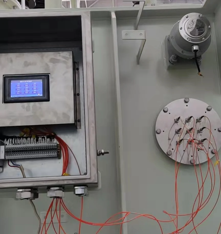
The preferred installation method is factory fit during transformer manufacturing. Probes are placed at specified winding positions, fibers are routed through the tank and terminated at penetrators in the flange assembly during tank assembly. The complete external assembly — flange, protective cover, extension cables, transmitter — is installed and commissioned before the transformer leaves the factory. Factory installation ensures optimal probe placement and eliminates the risk of probe displacement during oil filling and energization.
Retrofit Installation (Outage Required)
Retrofit installation is performed during a scheduled transformer outage when the unit is de-energized and the oil level is lowered sufficiently to expose the winding tops. Tank wall penetrations are made for the flange assembly, probes are inserted and secured at winding positions, and the external system is installed and tested before oil refilling. Retrofit scope and feasibility depend on transformer design, tank access, and outage duration available. Contact our engineering team with transformer drawings for a retrofit assessment.
Deployment Cases
Regional Transmission Utility — 220 KV Autotransformer Fleet
A regional transmission operator installed IF-TF systems on twelve 220 KV autotransformers at six substations as part of a fleet-wide مراقبة حالة المحولات الكهربائية upgrade. Each unit was fitted with a 6-channel configuration covering HV and LV windings on all three phases. Modbus-RTU data was integrated into the operator's existing substation automation system. Within the first operating season, two units showed winding temperature asymmetry under heavy load conditions that had not been visible from oil temperature alone. Cooling system inspection identified partially blocked radiator circuits on both units, which were cleaned during scheduled maintenance before any insulation damage occurred.
Industrial Cogeneration Plant — 110 KV GSU Transformer
A cogeneration facility operating a 110 KV generator step-up transformer required winding temperature monitoring to support dynamic loading above nameplate rating during peak demand periods. A 3-channel IF-TF system was factory-fitted on the HV winding. The real-time hot spot data, combined with the plant's load management system, allowed the operator to increase peak output by 8% while maintaining hot spot temperature within IEC 60076-7 thermal limits — a capacity gain that would not have been possible without direct winding temperature visibility.
Urban Substation Retrofit — 35 KV Distribution Transformers
An urban distribution operator retrofitted IF-TF 3-channel systems on eight 35 KV distribution transformers at a critical urban substation where transformer failure would affect a dense commercial load area. Installation was performed during a planned 48-hour outage window. The Modbus output connected to the substation's existing protection relay, replacing calculated hot spot temperature estimates with direct measurements. Post-installation monitoring showed that two transformers had been operating closer to thermal limits than the calculated estimates indicated — allowing load redistribution before the summer peak loading period.
Customization and OEM
The IF-TF system is available in fully customized configurations. Parameters adjustable at the time of order include channel count (1–18), fiber optic probe length (0–20 m), probe diameter, temperature range, flange dimensions and penetrator count, transmitter enclosure material and color, and communication output configuration. OEM and ODM supply is available for customers requiring branded equipment or application-specific modifications.
For projects requiring specific certifications beyond the standard CE, RoHS, and ISO 9001 — including UL, IECEx, ATEX, CSA, or TÜV — please specify at the time of inquiry as lead times and documentation requirements vary by certification body.
الأسئلة الشائعة
How is the IF-TF system different from a standard winding temperature indicator (WTI)?
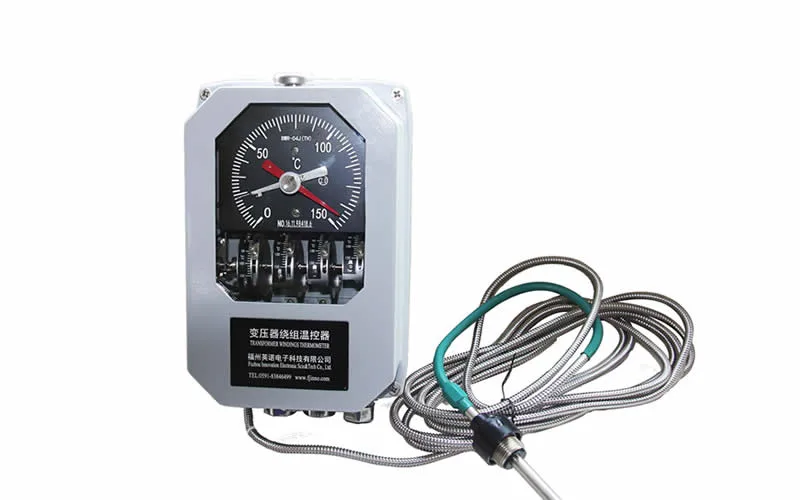
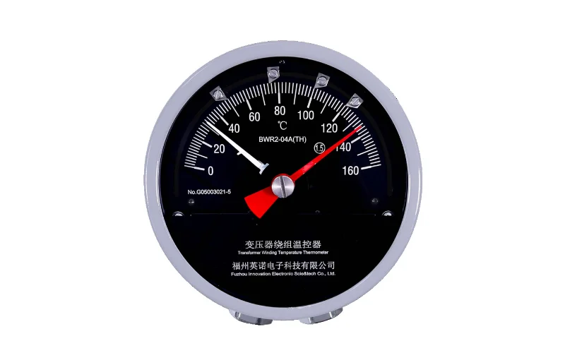
A conventional winding temperature indicator estimates hot spot temperature by adding a calculated thermal image — derived from load current — to the measured top oil temperature. It does not measure winding temperature directly. The IF-TF system places fiber optic probes in physical contact with the winding and measures actual temperature at that location. There is no estimation, no thermal model assumption, and no calibration drift. Under dynamic loading conditions, the calculated WTI estimate can diverge significantly from actual winding temperature. Direct measurement eliminates this uncertainty.
Can the system be integrated with our existing SCADA platform?
Yes. The RS485 / Modbus-RTU output uses a standard register map that is compatible with all major SCADA platforms, substation automation systems, and protection relays with Modbus client capability. A Modbus register map and integration guide are supplied with every system. For legacy systems requiring analog input only, the 4–20 mA output connects directly to existing analog input cards without any protocol work.
What happens if one probe fails?
A probe fault (open fiber, connector loss, or probe damage) is detected by the transmitter and reported as a channel fault via Modbus status register and front panel indication. The remaining channels continue operating normally. Probe replacement requires a transformer outage to access the internal winding location. External components — extension cables, connectors, transmitter — can be replaced without a transformer outage. We recommend maintaining one spare probe assembly per installation for rapid recovery.
How many probes are needed for a three-phase transformer?
The minimum recommended configuration for a three-phase oil-immersed transformer is three probes — one per phase at the top of the high-voltage winding. A 6-channel configuration adds a second probe per phase at the low-voltage winding, providing full coverage of both winding sets. For large power transformers or units with known thermal asymmetry, additional probes at multiple heights per winding column provide more detailed thermal mapping. Our engineering team will recommend a channel configuration based on your transformer's MVA rating, voltage class, and cooling type.
Is the penetrator installation permanent?
The penetrator and flange assembly is a permanent modification to the transformer tank wall. However, individual penetrators can be removed and replaced from outside the tank during a maintenance outage without disturbing the probe inside. The M14 × 1.0 thread and fluorine rubber O-ring seal provide a replaceable mechanical interface. The flange plate itself, once welded in position, remains as a permanent feature that can support replacement penetrators and probes for the life of the transformer.
What is the system warranty and lead time?
Standard warranty is 12 months from the bill of lading date. Lead time for standard configurations is 15–20 working days from order confirmation. Custom configurations — non-standard fiber lengths, special certifications, OEM branding — may require additional lead time depending on scope. Contact us with your configuration requirements for a specific lead time and quotation.
Can the system support dynamic transformer rating (DTR)?
Yes. Direct hot spot temperature measurement is the primary input required for real-time thermal modeling under IEC 60076-7, which underpins dynamic transformer rating calculations. With IF-TF data feeding into a DTR system, operators can safely increase loading above nameplate rating during periods when actual thermal conditions allow it — recovering capacity margin without compromising insulation life. Several utilities have deployed IF-TF systems specifically to enable DTR programs on transmission transformers.
Do you supply the complete system or components only?
We supply the complete assembled system — transmitter, probes, penetrators, flange assembly, protective cover, and extension cables — configured and tested as a matched set before shipment. Individual components are also available for replacement or for integration into existing installations. Full installation documentation, wiring diagrams, and Modbus register maps are included with every system shipment.
Get a Configuration Recommendation and Quote
Every transformer installation has different channel requirements, fiber lengths, flange access constraints, and integration needs. Send us your transformer nameplate data, single-line diagram, and monitoring requirements, and our engineering team will provide a specific system configuration recommendation with pricing within one business day.
Factory direct supply. In-house R&D and manufacturing. CE, RoHS, ISO 9001 certified. OEM/ODM available. Shipped globally.