Облачный и локальный мониторинг трансформаторов: SCADA, удаленный доступ и архитектура данных
Дата публикации:9 октября 2026 г., 16:52:40
- Local transformer monitoring keeps data, alarms and protection logic inside the substation or plant, while cloud-based monitoring sends selected data to a hosted platform for remote access and fleet-wide analysis.
- Neither model replaces the other: protection, fan control and trip logic must stay local, and the cloud adds visibility, storage and comparison across sites.
- A hybrid architecture with an edge gateway is the most common choice for utilities, industrial plants and data centers.
- Field devices that speak Modbus RTU/TCP, IEC 61850, RS485 or 4–20 mA can feed a local SCADA, a cloud gateway or both.
- Key decision factors are latency, availability, cybersecurity, data ownership, bandwidth and lifecycle cost.
- Slow-changing data such as gas readings suits cloud trending well, while second-by-second temperature control belongs on the local network.
- Security needs network segmentation, encrypted outbound connections, role-based access and audit logs under frameworks such as IEC 62443.
Содержание
- 1. What Is the Difference Between Cloud-Based and Local Transformer Monitoring?
- 2. Local Monitoring Architecture: Sensors, Controllers, Gateway and SCADA
- 3. Cloud-Based Monitoring Architecture: Edge Gateway, Secure Link and Hosted Platform
- 4. Cloud vs Local Comparison: Latency, Availability, Security, Cost and Control
- 5. What Must Stay Local: Protection, Fan Control and Trip Logic
- 6. What the Cloud Does Well: Remote Access, Fleet Trends and Reporting
- 7. Device Interfaces: Protocols and Outputs Available on INNOFZ Monitoring Equipment
- 8. Data Architecture: Polling, Time Stamps, Storage and Retention
- 9. Cybersecurity and Remote Access Controls
- 10. Choosing an Architecture: Decision Guide by Site Type
- 11. Implementation Steps and Common Mistakes
- 12. Frequently Asked Questions (FAQ)
1. What Is the Difference Between Cloud-Based и Local Transformer Monitoring? Definitions and Scope
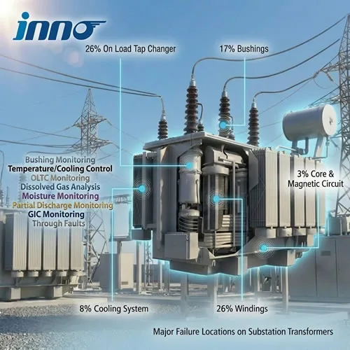
1.1 Local transformer monitoring means the sensors, controllers, SCADA or HMI, and data storage all sit on the site network. Operators see alarms and trends on local screens, and no data needs to leave the facility. This is the traditional model in substations and plants.
1.2 Cloud-based transformer monitoring sends selected measurements to a hosted platform over the internet or a private network. Users open dashboards from any location, compare many transformers in one view and keep long data histories without maintaining servers on site.
1.3 In practice, the question is rarely either/or. Most projects combine a local layer for control and protection with an optional remote layer for visibility. The choice affects equipment selection, network design and security planning from the start. For an overview of the underlying measurements, see the мониторинг трансформатора решение.
1.4 Terms Used in This Guide
- SCADA: supervisory control and data acquisition system used by utilities and plants.
- Edge gateway: a device that reads field protocols locally and forwards data outward.
- Historian: a database optimised for time-stamped process data.
- Hybrid architecture: local control plus selected remote or cloud services.
2. Local Monitoring Architecture: Датчики, Temperature Controllers, Gateway and SCADA Inside the Substation
2.1 A local architecture follows a layered pattern. Each layer has a clear job, and failure of one layer should not disable protection.
| Слой | Функция | Типовое оборудование |
|---|---|---|
| 1. Полевые датчики | Measure temperature, gas, discharge, load | Pt100, fiber optic probes, DGA sensors, PD sensors |
| 2. Controllers and monitors | Process signals, run local alarm, fan and trip logic | Temperature controllers, multi-channel transmitters, DGA monitor |
| 3. Полевая сеть | Carry data to the gateway | RS485 Modbus RTU, Ethernet, fiber network |
| 4. Gateway or RTU | Translate protocols for the control system | Шлюз подстанции, менеджер связи |
| 5. SCADA / HMI / historian | Display, alarm, store, report | On-site servers and operator stations |
2.2 Strengths of the Local Model
- Fast response, since data travels only across the site network.
- Works during internet outages.
- Data stays under the owner's control, which suits sensitive infrastructure.
- Fits existing substation automation, including IEC 61850 networks.
2.3 Limits of the Local Model
Remote engineers have limited visibility unless a VPN or remote desktop is set up. Comparing many sites requires a central SCADA or manual data collection. On-site servers also need maintenance, backup and patching. Learn how local dashboards are organised in transformer condition monitoring methods and strategy.
3. Cloud-Based Monitoring Architecture: Edge Gateway, Secure Link and Hosted Platform for Transformer Data
3.1 A cloud-connected design adds an outbound path from the site to a hosted platform. The local layers stay in place; the cloud is an additional consumer of the same data.
3.2 Typical Data Path
- Field devices measure and expose values through Modbus, IEC 61850 or analog outputs.
- An edge gateway on the site network polls the devices, adds time stamps and buffers data if the link drops.
- The gateway sends data outward over an encrypted connection, commonly using MQTT, HTTPS or OPC UA over TLS.
- The hosted platform stores the data, applies alarm rules and builds dashboards.
- Users sign in from a browser or mobile device, and notifications go out by email or messaging.
3.3 Outbound-Only Connections
3.3.1 Why Direction Matters
A well-designed system opens connections from the site to the platform rather than the other way around. This avoids exposing field devices to inbound internet traffic and fits the network zoning recommended in IEC 62443.
3.4 Store-and-Forward Buffering
If the internet link fails, the edge gateway should keep collecting data locally and send it when the link returns. This preserves the continuity of trends and event records.
3.5 What Gets Sent
Many projects forward only selected values: temperatures, alarm states, gas results, load summaries and device health. Raw high-speed data, such as waveform captures, often stays on site.
4. Cloud vs Local Comparison: Latency, Availability, Cybersecurity, Cost and Data Control
4.1 The table below summarises how the two models differ across the criteria that usually decide a project.
| Criterion | Местный мониторинг | Cloud-Based Monitoring |
|---|---|---|
| Время отклика | Immediate, on the site network | Seconds to minutes, depends on the link |
| Works without internet | Да | Needs buffering at the edge; remote views unavailable offline |
| Remote access | Requires VPN or remote desktop | Built in through a browser or mobile app |
| Multi-site comparison | Needs a central SCADA or manual export | Native fleet view |
| Data ownership and location | Fully on site | Depends on provider, region and contract |
| Cost pattern | Hardware, servers and maintenance up front | Subscription or service fee over time, lower up-front cost |
| Software upkeep | Owner patches and backs up servers | Provider manages the platform |
| Cybersecurity exposure | Smaller external footprint | Larger external footprint, needs strong controls |
| Scalability | Limited by site servers | Easy to add transformers and sites |
| Protection functions | Подходящий | Not suitable on its own |
4.2 Reading the Comparison
Local monitoring wins on speed, independence and control. Cloud monitoring wins on reach, scale and convenience. The hybrid approach captures both by keeping time-critical functions on site and using the cloud for supervision and analysis.
5. What Must Stay Local: Защита, Cooling Fan Control и Trip Logic on Transformer Controllers
5.1 Any function that protects the transformer or controls cooling must work without a network connection. Internet delays, outages or platform maintenance should never affect these actions.
5.2 Local Control Examples
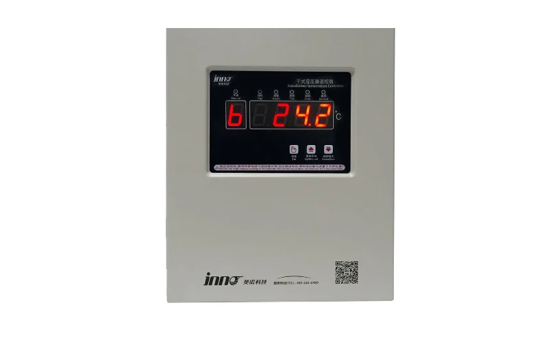
Этот Устройство интеллектуального мониторинга трансформатора сухого типа YN-XP502F-3T runs fan start and stop, winding over-temperature alarm and trip outputs on its own relay contacts rated 16 A / 250 VAC, with Modbus RTU for upstream communication. The IB-S201 dry type transformer temperature monitor and controller provides fan, alarm and trip outputs with optional 4–20 mA, RS485 or RS232 output.
| Функция | Where It Should Run | Reason |
|---|---|---|
| Trip on winding over-temperature | Local relay | Must act regardless of network state |
| Cooling fan start and stop | Local controller | Thermal response is continuous and time-sensitive |
| Sensor fault detection | Local controller | Prevents false readings from affecting protection |
| Local alarm indication | Local display and relay | Operators on site need immediate warning |
| Trend storage and reports | Local and/or cloud | Not time-critical |
| Fleet dashboards | Cloud or central SCADA | Needs data from many sites |
5.3 Temperature Settings Stay with the Controller
Fan and alarm thresholds are configured in the controller itself, not in the cloud. On the YN-XP502F-3T, the four settings (fan stop, fan start, alarm, trip) are adjustable through the device interface, and each higher threshold must be at least 5.0 °C above the previous one.
6. What the Cloud Does Well: Remote Access, Fleet-Wide Trends, Reporting and Notifications
6.1 Cloud platforms add value where distance and scale matter.
6.2 Strong Use Cases
- Multi-site operators: one screen showing the status of transformers across many substations, plants or campuses.
- Remote specialists: engineers review data from the office without traveling to every site.
- Long-term trending: years of gas, temperature and load history stored without local server limits.
- Reporting: scheduled reports for asset managers and auditors.
- Notifications: alarm messages sent to phones and email to the right people.
- Comparison between similar units: an outlier transformer becomes easier to spot.
6.3 Best-Suited Data Types
Slow-moving data is a natural fit. Online dissolved gas results, for example, arrive on a cycle measured in hours. The online dissolved gas analysis (DGA) monitoring system for transformer oil has an adjustable sampling cycle with a minimum of two hours or less, so trending and remote review work well on any link. Learn more about gas trending in transformer online DGA monitoring и анализ растворенных газов решение.
7. Device Interfaces: Протоколы and Outputs Available on INNOFZ Transformer Monitoring Equipment
7.1 Whether the project is local, cloud-connected or hybrid, the field devices need open interfaces. The table lists the interfaces published for several INNOFZ products. Any gateway or platform that supports these protocols can read the data.
| Product | Published Communication and Output Options |
|---|---|
| YN-XP502F-3T dry-type monitoring device | Modbus RTU, address 1–247, 1200–38400 bps (default 9600), parity none/odd/even; fan, alarm and trip relays |
| IB-S201 temperature monitor and controller | Optional 4–20 mA, RS485 or RS232; fan, alarm and trip outputs |
| Multi-channel fiber optic temperature system | RS485 Modbus; optional 4–20 mA; 1 to 64 channels; alarm output |
| Online DGA monitor | RS-485 (Modbus RTU/TCP), IEC 61850, RJ-45 Ethernet; optional 4–20 mA |
| Dry-type health monitoring system | RS485, RJ45 Ethernet, IEC 61850 fiber optic interface; analog and dry-contact inputs |
7.2 Where Each Product Fits
7.2.1 Temperature Systems
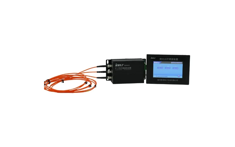
Этот многоканальная оптоволоконная система измерения и контроля температуры offers a temperature range of −40 °C to +240 °C, ±1 °C accuracy, 0.1 °C resolution and up to 64 channels. For smaller channel counts, see the IF-G3 3-channel module и 6-канальный демодулятор флуоресцентного сигнала, and for larger projects the 64-канальная система измерения температуры с использованием флуоресцентных оптоволоконных датчиков.
7.2.2 Station-Level Health Monitoring
Этот интеллектуальная система онлайн-мониторинга состояния трансформаторов сухого типа communicates through a fiber optic network and IEC 61850 for station-level integration, with RS485 and RJ45 Ethernet ports for other connections.
7.3 Protocol Choices
| Протокол | Типичная должность | Local SCADA | Cloud Gateway |
|---|---|---|---|
| Modbus RTU (RS485) | От устройства к шлюзу | Yes, through a gateway or RTU | Yes, read by edge gateway |
| Modbus TCP | Ethernet device or gateway link | Да | Да |
| IEC 61850 | Автоматизация подстанций | Yes, native | Through a protocol-converting gateway |
| 4–20 mA analog | Legacy panels and PLC inputs | Да | Through an analog-input gateway |
| MQTT / HTTPS / OPC UA | Gateway to platform | Optional | Common for outbound links |
8. Архитектура данных for Transformer Monitoring: Polling Intervals, Time Stamps, Storage Tiers and Retention
8.1 Good data design prevents gaps, duplicated values and unclear time references. Decide these points before purchasing hardware.
8.2 Polling and Reporting Rates
| Тип данных | Local Polling | Sent to Cloud |
|---|---|---|
| Температура намотки | Every 1 to 10 seconds | On change or 1-minute averages with maximum values |
| Fan, alarm and trip status | Every 1 to 5 seconds or on event | On every state change with time stamp |
| Load current and power | Every 1 to 5 seconds | 1-minute averages and peaks |
| Dissolved gas results | Each analysis cycle (hours) | Every result with device time stamp |
| Device health and communication state | Every few seconds | On change and as periodic heartbeat |
8.3 Time Synchronisation
Synchronise gateways and servers with NTP, or with IRIG-B or PTP where sequence-of-event accuracy matters. Use UTC internally and convert to local time only in dashboards.
8.4 Storage Tiers
8.4.1 Device Level
Devices keep their own records, which protects data during network outages. The YN-XP502F-3T stores historical temperatures, maximum values and event records with time information, and the DGA system retains at least 10 years of on-board measurement records.
8.4.2 Site Level
A local historian stores detailed data for operations and troubleshooting.
8.4.3 Cloud Level
The platform stores summarised or selected data for long-term trending and reporting. Define how long raw and summarised data is retained and who can export it.
8.5 Data Quality Flags
Mark each value as good, stale, out of range or substituted. When the connection to a device is lost, show the value as stale instead of repeating the last reading as if it were current.
9. Cybersecurity и Remote Access Controls for Cloud-Connected Transformer Monitoring
9.1 Connecting substation or plant equipment to an external platform makes security a design requirement. IEC 62443 provides a framework for industrial network zones, and regional rules such as NERC CIP may also apply.
9.2 Recommended Controls
| Управление | Цель |
|---|---|
| Network segmentation and firewalls | Isolate monitoring devices from corporate and public networks |
| Outbound-only connections | Avoid exposing field devices to inbound internet traffic |
| TLS encryption in transit | Protect data between the gateway and the platform |
| Role-based user access with multi-factor sign-in | Limit who can view or change settings |
| Read-only data path by default | Prevent remote changes to protection settings |
| Audit logs | Record sign-ins, changes and exports |
| Disabled unused ports and changed default passwords | Reduce the attack surface of devices and gateways |
| Firmware and configuration backups under change control | Allow safe recovery and traceability |
9.3 Keep Remote Writes Restricted
Remote users should view data and acknowledge alarms, but changing trip or fan thresholds should require on-site or tightly controlled access. Protection settings are best changed from the device interface during planned maintenance.
9.4 Data Ownership and Location
Before choosing a hosted platform, confirm where data is stored, who owns it, how it can be exported and what happens when the service ends. Utilities and critical infrastructure operators may need to keep data within a country or on a private cloud.
10. Choosing an Architecture: Decision Guide for Utilities, Industrial Plants, Data Centers and Renewable Sites
10.1 Use the table to match the architecture to the operating context.
| Site Type | Recommended Architecture | Key Reason |
|---|---|---|
| High-voltage utility substation | Local, with IEC 61850 and SCADA; optional controlled data export | Strict security, existing automation system |
| Single industrial plant | Local SCADA, optional remote view through VPN | Simple network, on-site team |
| Multi-site industrial or commercial portfolio | Hybrid with edge gateways and a central platform | One view of many transformers |
| Data center campus | Local BMS/EPMS integration plus central dashboard | Uptime focus and standard building systems |
| Remote or unmanned site | Hybrid with store-and-forward gateway | Visibility without frequent visits |
| Renewable energy fleet | Hybrid with fleet-level cloud trending | Many geographically spread transformers |
10.2 Sector Pages
Typical deployments are described for подстанции, power grid and utilities, renewable energy, производство электроэнергии и rail transit.
10.3 Questions to Settle First
- Which functions must keep working with no network connection?
- Does the owner allow any data to leave the site, and where may it be stored?
- Which protocols does the existing SCADA, BMS or EPMS accept?
- How many transformers and sites will be compared in one view?
- Who will maintain gateways, firmware and user accounts?
11. Implementation Steps and Common Mistakes in Local, Cloud and Hybrid Monitoring Projects
11.1 A phased approach reduces risk and keeps costs clear.
11.2 Implementation Steps
- Install field monitoring with local display, relay outputs and device-level storage.
- Connect devices to the local SCADA, BMS or EPMS using Modbus or IEC 61850.
- Test every alarm from sensor to screen, including communication loss.
- Add an edge gateway with outbound-only encrypted connectivity, if remote access is required.
- Select which values go to the platform and set reporting rates.
- Configure users, roles, notifications and audit logs.
- Document settings, register maps, network diagrams and responsibilities.
11.3 Common Mistakes
- Relying on the cloud for trip or fan control.
- Opening inbound firewall ports to field devices.
- Sending every raw value, which inflates bandwidth and storage without improving decisions.
- Ignoring time synchronisation, so events from different devices cannot be lined up.
- Not defining who acknowledges alarms and who may change settings.
- Skipping a communication-loss alarm, which hides stale data.
11.4 Retrofit and New Build
For existing transformers, add temperature and gas monitoring first and connect them to the available network. For new transformers, specify fiber optic sensors and communication requirements during manufacture, using guidance from fiber optic temperature measurement in transformers и transformer winding hot spot temperature measurement and monitoring sensors.
11.5 Talk to an Engineer
Send your transformer type, number of sites, SCADA platform and security requirements through contact us for a configuration proposal. You can also review the поддержка page, our certificates and learn more about us.
12. Frequently Asked Questions (FAQ) about Cloud-Based и Local Transformer Monitoring
1. What is the main difference between cloud-based and local transformer monitoring?
Local monitoring keeps data, alarms and displays on the site network, while cloud-based monitoring sends selected data to a hosted platform for remote access and multi-site comparison.
2. Can a cloud platform replace SCADA?
Not for control and protection. Cloud platforms provide visibility, storage and reporting, while SCADA, controllers and relays handle time-critical supervision and protective actions on site.
3. Should trip and cooling fan control run in the cloud?
No. These functions must run locally on the controller and its relay contacts so they continue to work during network or internet outages.
4. What is a hybrid transformer monitoring architecture?
It is a design where local controllers and SCADA handle protection and operations, and an edge gateway forwards selected data to a central or cloud platform for remote access and analysis.
5. Which protocols do transformer monitoring devices use?
Common protocols are Modbus RTU over RS485, Modbus TCP, IEC 61850 and 4–20 mA analog signals. For example, the YN-XP502F-3T uses Modbus RTU and the online DGA monitor supports Modbus RTU/TCP and IEC 61850.
6. How is data sent securely from a substation to a cloud platform?
Through an edge gateway that opens outbound, encrypted connections such as MQTT, HTTPS or OPC UA over TLS, combined with network segmentation, firewalls and role-based access.
7. What happens to monitoring data when the internet connection fails?
Local protection and displays continue unaffected. A gateway with store-and-forward buffering keeps collecting data and sends it when the connection returns, and devices keep their own records as well.
8. How much data should be sent to the cloud?
Usually selected values only: temperatures, alarm states, gas results, load summaries and device health. Averages and event-based reporting reduce bandwidth and storage without losing important information.
9. Is cloud monitoring suitable for critical infrastructure?
It can be, when security zones, outbound-only links, encryption, access control and data location rules meet the operator's requirements. Many critical sites keep control entirely local and share only limited data externally.
10. How do I choose between cloud, local and hybrid monitoring?
Start with which functions must survive a network outage, then consider data ownership rules, existing SCADA, the number of sites to compare and who will maintain the system. Single sites often start local, while multi-site portfolios usually benefit from a hybrid design.