

Temperaturanstieg bei Transformatoren: Grenzwerte und Nennwerte
Veröffentlichungsdatum:2026年9月6日 15:42:14
- Transformer winding temperature alarm and trip settings should be based on the transformer's thermal design, insulation system, cooling method and manufacturer limits—not copied from another transformer.
- A practical temperature protection scheme normally includes separate stages for cooling control, high-temperature alarm and trip.
- A conventional winding temperature indicator (WTI) is suitable when operators need local indication, alarm contacts and cooling control based on winding thermal indication.
- For critical power transformers requiring direct winding hot-spot measurement, embedded fiber optic temperature sensors can provide actual temperatures from selected winding locations.
- If the transformer is connected to PLC, DCS or SCADA, verify required outputs such as relay contacts, RS485, Modbus or analog signals before selecting the monitoring device.
- For retrofit projects, first confirm whether the existing requirement is simply to replace a WTI or to upgra de the transformer to a complete online temperature monitoring system.
Setting the correct transformer winding temperature alarm and trip values is not only a protection issue—it also affects cooling control, transformer loading, operating continuity and the selection of the temperature monitoring equipment.
For many retrofit and new-transformer projects, the real question is not simply “What temperature should I set?” Engineers must first determine whether the system requires a traditional winding temperature indicator, direct embedded hot-spot sensors, multi-channel monitoring, or integration into an existing transformer condition monitoring platform.
This guide focuses on the practical decisions needed when specifying, replacing or upgrading transformer winding temperature monitoring equipment.
Table of Contents
- 1. What Are Transformer Winding Temperature Alarm and Trip Settings?
- 2. Alarm, Trip and Cooling Control: What Is the Difference?
- 3. How to Determine Transformer Winding Temperature Settings
- 4. WTI Alarm and Trip Setting Example
- 5. Winding Temperature Indicator vs Direct Fiber Optic Measurement
- 6. When Should You Use a Transformer Winding Temperature Indicator?
- 7. When Is Fiber Optic Winding Temperature Monitoring Better?
- 8. Transformer Oil Temperature vs Winding Temperature Protection
- 9. Relay, PLC and SCADA Requirements
- 10. Retrofit and Replacement Selection Guide
- 11. Information to Provide When Requesting a Quotation
- 12. Common Alarm and Trip Setting Mistakes
- 13. Frequently Asked Questions
- 14. Selecting the Right Transformer Temperature Monitoring Equipment
1. What Are Transformer Winding Temperature Alarm and Trip Settings?
1.1 Transformer Winding Temperature Alarm Setting
Die transformer winding temperature alarm setting is a threshold at which the temperature monitoring device indicates that winding thermal conditions have reached an abnormal or predefined operating level.
An alarm normally gives operators time to investigate the transformer before a trip becomes necessary. Depending on the system, the alarm signal can be provided through a local contact, remote relay, PLC, DCS or SCADA system.
When selecting a replacement device, verify the number and type of alarm contacts rather than assuming every winding temperature indicator provides the same outputs.
1.2 Transformer Winding Temperature Trip Setting
Die transformer winding temperature trip setting is normally a higher protection threshold used to initiate shutdown or provide a trip signal to another protection device.
The trip value should follow the transformer's approved operating limits and protection philosophy. It should not be selected only because another transformer uses a particular temperature.
The trip function is especially important for unattended substations and critical industrial transformers where excessive winding temperature could continue without immediate operator intervention.
1.3 Cooling Start and Stop Settings
Many transformer winding temperature devices also control cooling equipment before the alarm stage is reached.
A typical control sequence may include:
- Normal transformer operation
- Cooling fan or pump start
- High-temperature alarm
- High-high-temperature alarm or trip
This staged approach allows the cooling system to respond before protection requires transformer shutdown.
2. Transformer Temperature Alarm, Trip and Cooling Control: What Is the Difference?
| Funktion | Zweck | Typical Action | Equipment Requirement |
|---|---|---|---|
| Cooling Start | Increase heat removal | Start fan or pump | Control relay/output |
| Cooling Stop | Stop unnecessary cooling after temperature decreases | Stop fan or pump | Control relay with appropriate hysteresis |
| High Temperature Alarm | Warn operator of abnormal thermal condition | Alarm indication / SCADA event | Alarm relay or digital communication |
| High-High Alarm | Provide additional warning level | Escalated alarm | Additional configurable output |
| Trip | Protect transformer from unacceptable thermal condition | Trip command to protection circuit | Dedicated output / protection integration |
The number of required stages should therefore be defined before purchasing the monitoring device. A simple local indicator may not be sufficient if the project requires fan control, two independent alarms, trip output and remote communications.
3. How to Determine Transformer Winding Temperature Alarm and Trip Settings
3.1 Start With Transformer Manufacturer Limits
The transformer manufacturer's thermal design should be the primary reference for winding temperature settings.
Before configuring a WTI or online monitoring system, obtain:
- Normal operating temperature range
- Permitted winding temperature
- Cooling start requirements
- Alarm threshold
- Trip threshold
- Cooling method
- Insulation system
- Transformer loading requirements
A monitoring device should implement the transformer protection philosophy rather than define it independently.
3.2 Consider Transformer Type
Oil-immersed and dry-type transformers should not automatically use the same temperature protection settings.
For dry-type equipment, a dedicated dry-type transformer temperature monitor and controller can combine sensor inputs, fan control, alarms and trip signals.
For liquid-immersed power transformers, winding thermal indication is commonly combined with oil-temperature measurement and transformer cooling control.
3.3 Consider Load and Cooling Conditions
Alarm thresholds should also be interpreted together with transformer load and cooling-system status.
If the winding temperature increases while load remains stable, engineers may need to investigate:
- Cooling fan failure
- Oil pump failure
- Restricted cooling path
- High ambient temperature
- Abnormal local heating
- Sensor or indicator problem
This is why critical installations often benefit from a broader transformer monitoring system rather than an isolated temperature gauge.
4. Transformer Winding Temperature Alarm and Trip Setting Example
There is no universal alarm and trip temperature that should be copied into every transformer. However, the following example shows how a multi-stage protection philosophy may be structured.
| Stage | Illustrative Setting | Action |
|---|---|---|
| Normal | Below 90°C | Normal operation |
| Cooling Start | 90°C | Start cooling equipment |
| High Temperature Alarm | 100 °C | Alarm operator / SCADA |
| Trip | 110°C | Initiate protection trip |
Wichtig: the 90°C / 100°C / 110°C values above are an illustrative control example only. They are not recommended universal transformer settings. Actual values must be taken from the transformer manufacturer, insulation system, protection study and project specification.
The purpose of the example is to show why a monitoring device may require several independently configurable outputs.
4.1 Why the Temperature Difference Between Stages Matters
Cooling, alarm and trip settings should not be configured so closely that normal measurement variation causes frequent relay switching or nuisance alarms.
Likewise, excessive separation between alarm and trip may reduce the operator's ability to respond before the transformer reaches the protection threshold.
The required hysteresis and delay should therefore be part of the device-selection process.
5. Winding Temperature Indicator vs Direct Fiber Optic Temperature Measurement
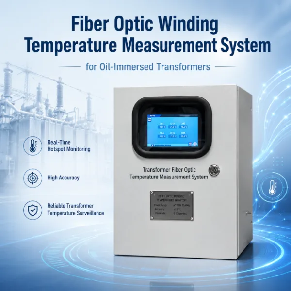
This is one of the most important choices when specifying transformer winding temperature monitoring.
| Artikel | Winding Temperature Indicator | Embedded Fiber Optic Sensor |
|---|---|---|
| Measurement Approach | Conventional winding thermal indication | Direct temperature at installed probe location |
| Embedded Inside HV Winding | Normally not required | Yes, when direct hot-spot measurement is required |
| Local Display | Common | Depends on interrogator/system |
| Kühlungssteuerung | Common application | Can be implemented through monitoring system |
| Alarm / Trip | Available depending on model | Available through system configuration |
| EMI Immunity at Sensing Point | System dependent | Excellent for optical sensing |
| Best Fit | Conventional transformer temperature indication and protection | Direct winding hot-spot monitoring |
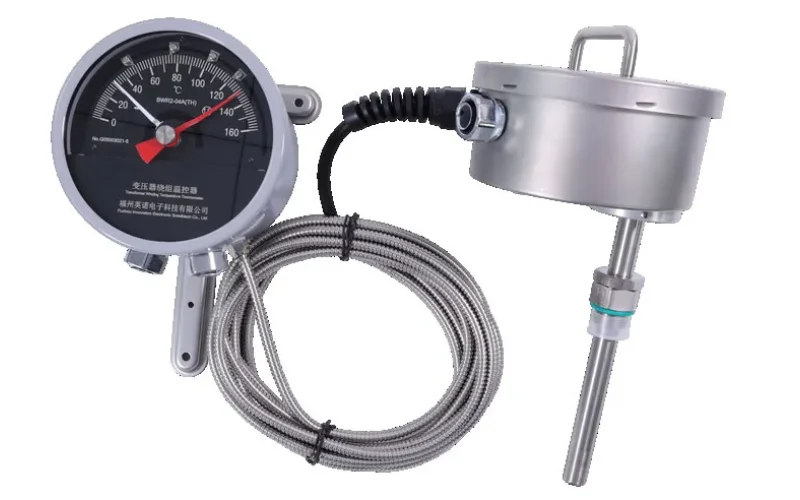
If the requirement is to replace a conventional WTI and retain familiar local indication and alarm contacts, an instrument such as the Temperaturanzeige für die Transformatorwicklungen des BWR2 may be the appropriate product category.
If the project requires actual embedded winding temperature measurements, the correct solution is different. A fiber optic temperature sensor for transformer winding hot spot monitoring measures the selected physical point directly.
6. When Should You Use a Transformer Winding Temperature Indicator?
A conventional transformer winding temperature indicator is suitable when the project requires functions such as:
- Local winding temperature indication
- Cooling fan or pump control
- High-temperature alarm
- Trip contact
- Replacement of an existing mechanical or electrical WTI
- Integration with existing transformer control wiring
For projects requiring a traditional WTI configuration, INNO offers the BWR-04/06AJTH transformer winding temperature indicator und Temperaturanzeige für die Transformatorwicklungen des BWR2.
6.1 What to Check When Replacing an Existing WTI
Before requesting a replacement, provide:
- Existing WTI model
- Temperaturbereich
- Number of alarm contacts
- Contact switching sequence
- Cooling-control requirements
- Remote transmission requirement
- 4–20 mA requirement, if applicable
- Panel mounting dimensions
- Probe/capillary requirements where applicable
A photograph of the old nameplate and wiring diagram can significantly reduce replacement-selection errors.
7. When Is Fiber Optic Winding Temperature Monitoring Better?
7.1 Direct Transformer Winding Hot-Spot Measurement
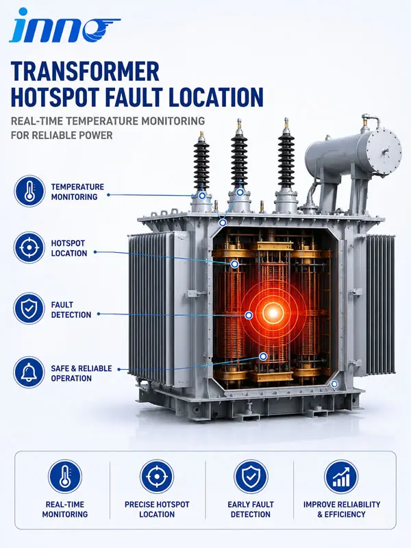
For a new power transformer or major refurbishment, the operator may want to know the actual temperature inside selected winding regions rather than only a conventional winding temperature indication.
Embedded optical probes can be installed close to predicted thermal hot spots during transformer manufacturing.
For this application, see the dedicated transformer winding hot spot monitoring solution.
7.2 High-Voltage and Strong Electromagnetic Environments
Fiber optic probes are especially useful where conventional electrical sensing presents isolation or electromagnetic-interference challenges.
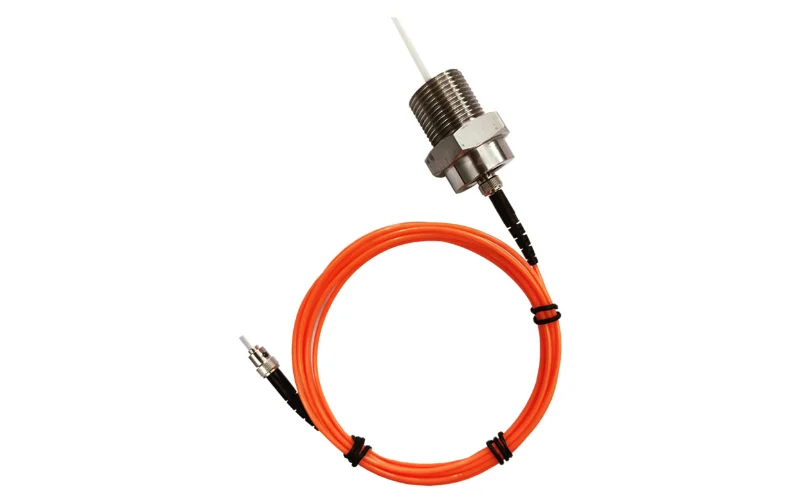
A polyimide fiber optic temperature sensor for transformer windings can be embedded at selected locations, while the electronic monitoring unit remains outside the high-voltage winding region.
For a wider comparison of measurement methods, see high voltage temperature measurement.
7.3 Multi-Point Transformer Winding Monitoring
One temperature point may not be enough for a three-phase transformer with several critical winding zones.
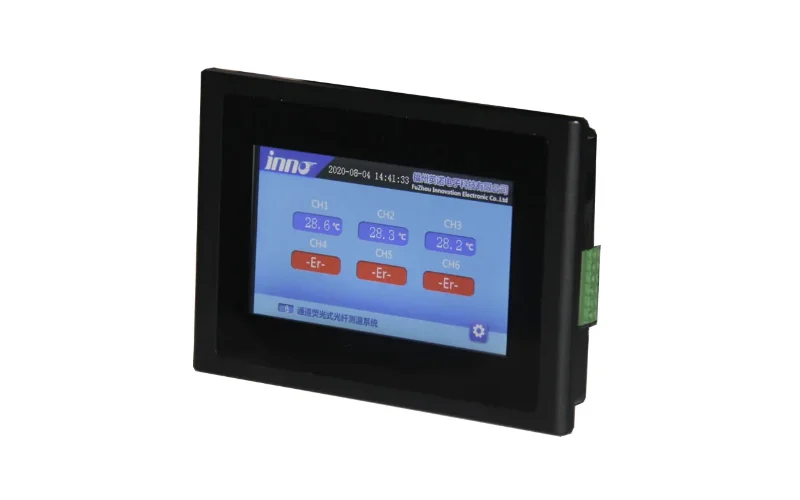
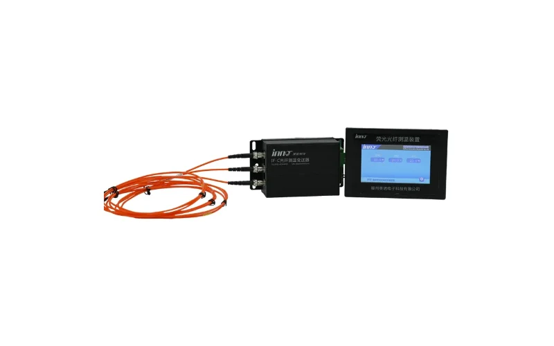
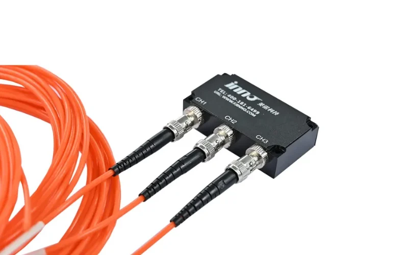
If direct measurements are needed across multiple phases or HV/LV windings, a multi-channel fiber optic temperature measurement and monitoring system can collect several embedded temperature channels in one platform.
The number of sensors should be determined from transformer thermal design rather than selected only according to the maximum channel count available.
8. Transformer Oil Temperature vs Winding Temperature Alarm Settings
Oil temperature and winding temperature are different thermal parameters and may require different protection settings.
8.1 Transformer Oil Temperature Monitoring
An oil temperature indicator measures transformer oil temperature rather than winding temperature.
For conventional oil-temperature indication, see the BWY2-Transformatoröl-Temperaturanzeige.
8.2 Why OTI and WTI Should Not Be Confused
| Device | Primary Parameter | Typical Function |
|---|---|---|
| OTI | Temperatur des Transformatoröls | Oil temperature indication, alarm and cooling-related functions |
| WTI | Winding thermal indication | Winding temperature indication, cooling control, alarm and trip |
| Fiber Optic Sensor | Direct local winding temperature | Embedded winding hot-spot measurement |
Critical power transformers may use all three types of temperature information rather than choosing only one.
9. Transformer Temperature Alarm Relay, PLC and SCADA Requirements
9.1 Relay Outputs
Before selecting a transformer temperature monitoring device, define how many independent relay functions are required.
For example:
- Fan start
- Fan stop
- Alarm 1
- Alarm 2
- Trip
- Sensor fault
If several independent outputs are required, confirm them during quotation rather than after installation.
9.2 Analog Temperature Transmission
Some substations and transformer monitoring systems require an analog temperature signal for remote acquisition.
If 4–20 mA or another analog signal is required, include this requirement in the inquiry because it can affect the selected device configuration.
9.3 RS485 and Modbus Integration
Modern transformer temperature monitoring increasingly requires digital communication to a PLC, DCS, SCADA or condition monitoring platform.
Depending on model and system configuration, communication may include RS485 or Modbus interfaces.
For applications that require more than a standalone temperature device, see the complete transformer temperature monitoring solution.
10. Transformer Winding Temperature Monitoring Retrofit and Replacement Guide
10.1 Replace Like-for-Like When the Existing System Still Meets the Requirement
If the existing transformer only requires local winding indication, cooling contacts and alarm/trip outputs, replacing the WTI with a compatible modern unit may be the simplest solution.
10.2 Upgrade When Remote Monitoring Is Required
A replacement project is also an opportunity to upgrade from local indication to remote monitoring.
Typical upgrade requirements include:
- 4–20 mA temperature transmission
- RS485 / Modbus
- Remote alarm status
- Temperature trend recording
- PLC or SCADA integration
- Multiple temperature channels
10.3 Do Not Promise Embedded Hot-Spot Measurement in a Simple Retrofit
Direct embedded fiber optic winding probes are normally easier to install during transformer manufacturing or major refurbishment.
If the transformer is already sealed and operating, replacing a WTI does not automatically provide direct internal winding hot-spot measurement.
This distinction is important when comparing a conventional WTI replacement with a new fiber optic temperature measurement system for oil-immersed transformers.
11. What to Provide When Requesting a Transformer Temperature Monitoring Quotation
Providing the following information allows a supplier to select the correct WTI, temperature controller or online monitoring system much faster.
| Information | What to Provide |
|---|---|
| Transformatortyp | Oil immersed / dry type |
| Rated Power | MVA / kVA |
| Voltage Class | HV / LV voltage |
| Existing Device | Model and nameplate photo |
| Measurement Requirement | Oil temperature / winding indication / direct winding hot spot |
| Kühlungssteuerung | Fan / pump stages required |
| Alarm Outputs | Number of alarm and trip contacts |
| Analog Output | 4–20 mA or other requirement |
| Kommunikation | RS485 / Modbus / PLC / SCADA |
| Number of Temperature Points | 1 / 3 / 6 / multi-channel |
| Installation | New transformer / retrofit / replacement |
If you are unsure which architecture is appropriate, send this information through the INNO contact page and specify whether the project is a new installation, replacement or monitoring-system upgrade.
12. Common Transformer Winding Temperature Alarm and Trip Setting Mistakes
12.1 Copying Settings From Another Transformer
Two transformers with similar power ratings can still have different winding designs, insulation systems, cooling methods and permissible temperatures.
Alarm and trip settings should therefore be transformer-specific.
12.2 Confusing Oil Temperature With Winding Temperature
OTI and WTI measure or represent different thermal parameters. Using one threshold simply because it is used for the other can lead to an inappropriate protection strategy.
12.3 Selecting a Device Before Defining the Required Outputs
A common procurement problem is selecting the temperature range first and checking relay outputs only afterward.
For practical replacement projects, output configuration may be as important as the temperature range.
12.4 Ignoring Communication Requirements
If SCADA integration is likely in the future, selecting a device with only local indication may create unnecessary replacement work later.
12.5 Assuming WTI Is Direct Winding Hot-Spot Measurement
A conventional WTI and an embedded fiber optic probe provide different kinds of thermal information.
If actual internal winding temperature is required, specify direct winding hot-spot measurement during the equipment-selection stage.
12.6 Setting Alarm and Trip Too Close Together
Alarm should normally provide enough operating margin for investigation or corrective action before a trip condition occurs.
The exact separation, delay and hysteresis should be defined by the transformer's protection philosophy rather than a generic rule.
13. Frequently Asked Questions About Transformer Winding Temperature Alarm and Trip Settings
13.1 What should the transformer winding temperature alarm be set to?
There is no universal alarm setting. Use the transformer manufacturer's approved temperature limits, insulation system, cooling design and protection requirements. The WTI or monitoring system should then be configured to match those requirements.
13.2 What should the transformer winding temperature trip setting be?
The trip threshold should be based on the maximum permissible thermal condition defined for that transformer. It is normally set above the warning alarm level and should be coordinated with the overall transformer protection scheme.
13.3 Should cooling start before the temperature alarm?
In many transformer control schemes, cooling is initiated before the high-temperature alarm so that the system has an opportunity to reduce temperature without operator intervention. Actual settings depend on transformer design.
13.4 What is the difference between WTI alarm and OTI alarm?
WTI relates to transformer winding thermal indication, while OTI relates to transformer oil temperature. Their settings and intended protection functions should be evaluated separately.
13.5 Can a winding temperature indicator control transformer cooling fans?
Yes, when the selected WTI includes the required configurable contacts or outputs. Confirm the number and switching functions of the contacts before ordering.
13.6 Can a transformer WTI provide a trip output?
Many transformer winding temperature indicators are designed to support alarm and trip functions, but the exact contact arrangement depends on model. Verify the required outputs against the product configuration.
13.7 When should fiber optic temperature sensors be used instead of a WTI?
Fiber optic sensors should be considered when direct temperature measurement is required inside high-voltage transformer windings, especially for selected winding hot spots and multi-point monitoring.
13.8 Can fiber optic temperature monitoring provide alarms and trips?
Yes. The optical probe measures temperature, while the interrogator or monitoring system can process the temperature values and provide alarm, communication or control outputs depending on configuration.
13.9 Can an old transformer WTI be replaced without changing the transformer?
Often yes, if a compatible replacement can match the existing measurement arrangement, mounting and output requirements. Provide the old model number, nameplate, photos and wiring requirements when requesting a replacement.
13.10 What information is needed to select a transformer temperature monitoring system?
At minimum, provide transformer type, rated power, voltage class, required temperature points, alarm/trip requirements, communication interface and whether the project is a retrofit or new transformer installation.
14. Selecting the Right Transformer Winding Temperature Monitoring Equipment
The correct transformer winding temperature alarm and trip system depends on what information and control functions the operator actually needs.
If the requirement is conventional winding indication, cooling control and relay outputs, a transformer winding temperature indicator may be sufficient.
If the requirement is direct internal winding hot-spot measurement, consider embedded fiber optic winding temperature sensors.
If several winding points must be monitored and transmitted to a PLC or SCADA platform, a multi-channel fiber optic temperature monitoring system may be more appropriate.
For projects requiring temperature together with additional transformer condition parameters, start with the broader transformer monitoring solution.
Need help selecting a WTI, fiber optic winding sensor or transformer temperature monitoring system? Send the transformer rating, voltage class, existing device model, number of monitoring points and required alarm/communication outputs through Contact INNO for configuration and quotation.
Related Transformer Temperature Monitoring Products and Solutions
- BWR2-Anzeige für die Wicklungstemperatur des Transformators
- BWR-04/06AJTH Transformer Winding Temperature Indicator
- Temperaturüberwachung von Transformatoren
- Überwachung von Hotspots in Transformatorwicklungen
- Glasfaser-Temperatursensor zur Überwachung von Hotspots in Transformatorwicklungen
- Mehrkanaliges Glasfaser-Temperaturmess- und -überwachungssystem







