

مراقبة حالة المحولات: الطرق والمعلمات وأجهزة الاستشعار واستراتيجية المراقبة عبر الإنترنت
发布时间:2026年9月24日 12:36:53
Transformer condition monitoring is the continuous or periodic assessment of a transformer's thermal, chemical, electrical and mechanical state. Its purpose is to judge the health of the asset, detect developing faults early and support maintenance decisions. A single measured value, such as oil temperature or load current, shows only how the transformer is operating at that moment. Condition monitoring combines several indicators and follows how they change over time, so engineers can tell whether the transformer's insulation, windings, bushings, tap changer and oil are deteriorating.
Not every transformer needs every monitoring parameter. The right monitoring configuration depends on the transformer type, its criticality, its operating conditions, its known failure risks and the monitoring infrastructure already in place.
- Transformer condition monitoring combines thermal, chemical, electrical and mechanical indicators. No single measurement gives a complete picture of transformer health.
- The most commonly monitored parameters are winding hot spot temperature, top-oil temperature, dissolved gases, partial discharge, bushing insulation, OLTC condition, oil moisture, and oil level and pressure.
- Online monitoring and periodic testing complement each other. Online monitoring shows trends and events between inspections, and periodic testing provides detailed diagnostics and verification.
- The monitoring strategy should follow the transformer's type, rating, criticality and likely failure modes, not a fixed checklist of every available technology.
- Monitoring data is most useful when it is compared against a baseline, trended, correlated across parameters and linked to defined maintenance actions.
ما المقصود بمراقبة حالة المحولات؟
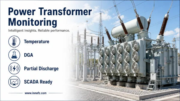
Transformer condition monitoring is the practice of collecting and interpreting data to assess the health of a transformer. The data can come from permanent online sensors, from periodic tests and inspections, or from both. The aim is to find degradation early, while there is still time to plan an intervention, rather than learning about a problem through a trip, a failure or an unplanned outage.
It is useful to separate operational measurement from condition assessment:
- Operational measurement reports present values such as load current, oil temperature or tap position. It supports day-to-day operation and protection.
- Condition assessment interprets those values and others in context: how they compare with the transformer's own history, how fast they are changing and whether several indicators point to the same developing problem.
Condition assessment is the foundation of condition-based maintenance. In condition-based maintenance, inspections, oil treatment, testing or repairs are scheduled according to the actual state of the equipment rather than fixed time intervals alone. For most asset owners the practical goal is not to eliminate periodic maintenance. The goal is to target it better and to reduce the risk of undetected deterioration between maintenance visits.
What Parameters Are Used for Transformer Condition Monitoring?
Each monitored parameter reflects a different part of the transformer or a different degradation mechanism. The table below summarizes the parameters most often used and where each typically applies.
| معلمة الرصد | What It Indicates | Typical Monitoring Method | Applicable Transformer Types |
|---|---|---|---|
| Winding / hot spot temperature | Thermal stress on winding insulation. Hot spot temperature is a primary driver of insulation aging. | Direct fiber optic probes in the winding, or indirect calculation from top-oil temperature and load (winding temperature indicator or thermal model) | Oil-immersed power and distribution transformers. Dry-type transformers (typically embedded temperature sensors in the windings). |
| Top-oil temperature | Overall thermal state of the transformer and cooling system performance | Temperature sensor (e.g. RTD) in a thermowell, oil temperature indicator | Oil-immersed transformers |
| تحليل الغازات المذابة (DGA) | Internal faults such as overheating, arcing and partial discharge, and cellulose insulation involvement | Laboratory analysis of oil samples, or online single-gas or multi-gas DGA monitors | Oil-immersed transformers |
| Partial discharge (PD) | Localized insulation defects and deterioration of the dielectric system | UHF sensors, HFCT sensors, acoustic emission sensors, offline electrical PD testing | Oil-immersed and dry-type transformers, especially high-voltage or critical units |
| حالة الجلبة | Changes in bushing insulation, such as moisture ingress, partial breakdown of capacitive layers or aging | Online capacitance and dissipation factor (tan delta / power factor) measurement via the bushing test tap, periodic offline testing | Transformers with condenser-type bushings, typically higher-voltage units |
| OLTC condition | Mechanical and electrical health of the on-load tap changer: drive mechanism, contacts and switching behavior | Motor current or power, tap position, operation counting, temperature differential, vibro-acoustic methods | Transformers equipped with on-load tap changers |
| Oil moisture | Moisture in the insulation system, which affects dielectric strength and accelerates aging | Online moisture-in-oil sensors, laboratory moisture analysis | Oil-immersed transformers |
| Oil level / pressure | Leaks, conservator or preservation system problems, gas accumulation, internal pressure events | Oil level gauges, gas-actuated (Buchholz) relays, pressure relief devices, pressure sensors | Oil-immersed transformers |
| Load / current | Operating stress. Load is the context needed to interpret temperature and other trends. | Current transformers, existing metering or protection data | All transformer types |
The following sections explain what each of the main parameters tells engineers and what its limitations are.
Winding and Hot Spot Temperature
Insulation aging in a transformer is strongly temperature-dependent, and the hottest point in the winding largely determines how quickly the paper insulation in that region deteriorates. This hot spot is usually hotter than the top oil, and its location depends on winding design, cooling arrangement and load. Hot spot temperature therefore bears directly on loading decisions, overload capability and remaining insulation life.
There are two general approaches to determining hot spot temperature:
- Indirect estimation. A winding temperature indicator or a thermal model calculates hot spot temperature from top-oil temperature, load current and design parameters. This approach is widely used and practical, but its accuracy depends on how well the model matches the real transformer, including cooling conditions and transient behavior.
- Direct measurement. Fiber optic temperature probes are installed at the expected hot spot locations inside the winding. Optical fibers are dielectric and are not affected by electromagnetic interference, so they can be placed in high-voltage regions where metallic sensors are unsuitable. Direct measurement is especially valuable for design verification, heat-run testing, dynamic loading and critical assets.
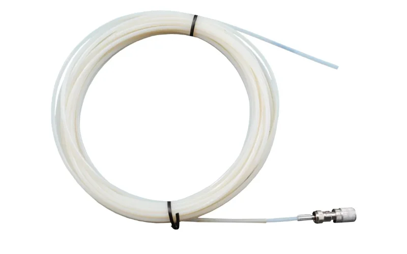
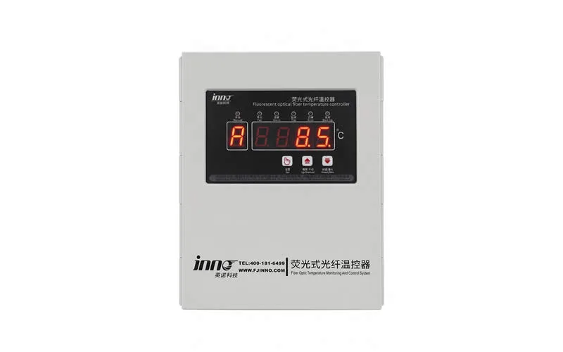
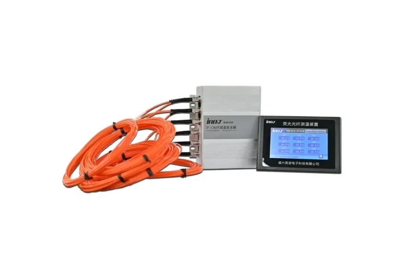
An important practical point is that direct winding probes normally have to be installed during manufacture or during a major rewinding or refurbishment. They generally cannot be added to an existing transformer in service. This should be considered early when specifying new transformers. For probe types and placement, see our guide to transformer winding hot spot temperature measurement. A fiber optic temperature sensor for transformer winding hot spot monitoring is an example of the probe type used in this application. The broader system approach is described on the fiber optic temperature monitoring page.
Dissolved Gas Analysis (DGA)
When oil and cellulose insulation are exposed to thermal or electrical stress, they break down and produce characteristic gases that dissolve in the oil. Measuring these gases is one of the most informative ways to detect internal faults in oil-immersed transformers, including faults that no external measurement would show.
In condition assessment, DGA contributes the following:
- It detects developing internal faults such as overheating, arcing and partial discharge.
- It helps indicate whether cellulose (paper) insulation is involved, mainly through carbon oxides.
- It shows how fast gases are being generated. The rate of change is often more meaningful than any single concentration.
DGA results should always be interpreted against the transformer's own history and in combination with other data. Fault-type interpretation methods are a large topic in their own right and are covered in a separate article. For system options, see transformer DGA monitoring.
التفريغ الجزئي
Partial discharge is a localized electrical discharge that only partially bridges the insulation between conductors. It can come from voids, contamination, sharp edges, floating potentials or degraded insulation. Sustained PD erodes insulation and can develop into breakdown, so PD activity is a direct indicator of dielectric condition.
PD monitoring helps engineers to:
- detect insulation defects before they progress,
- track whether PD activity is stable, increasing or intermittent,
- support source location and severity assessment when combined with other methods, and
- correlate electrical activity with DGA findings such as hydrogen generation.
Online PD measurement in substations must deal with external interference and noise, so sensor selection, installation and signal processing strongly affect how useful the data is. For monitoring approaches, see partial discharge monitoring.
Transformer Bushing Condition
Bushings are a known contributor to transformer failures, and a bushing failure can damage the main tank and nearby equipment. High-voltage condenser-type bushings have a graded insulation structure. Changes in the insulation, such as moisture ingress, aging or breakdown between capacitive layers, show up as changes in capacitance and dissipation factor (tan delta or power factor).
Periodic offline testing measures these values while the transformer is de-energized. Online bushing monitoring typically connects to the bushing test tap and tracks changes in capacitance and dissipation factor under service voltage, often by comparing the three phases or by referencing another signal source. The absolute value matters less than the change from the bushing's own baseline and any deviation between phases. See transformer bushing monitoring for more detail.
مراقبة حالة OLTC
The on-load tap changer is the only major moving component in most power transformers. It combines a motor drive mechanism, a switching system and contacts that carry and interrupt load current. It has its own failure modes, largely separate from those of the core and windings: mechanical wear, drive or linkage problems, contact wear and coking, and timing or sequence faults.
For this reason the OLTC is best treated as a separate subsystem with its own monitoring indicators, such as:
- motor current or power during operation, which reflects mechanical load and drive condition,
- tap position and operation count, which support maintenance planning based on switching duty,
- temperature difference between the OLTC compartment and the main tank, where applicable, and
- vibro-acoustic signatures of the switching sequence, which are compared against reference signatures.
DGA of the OLTC compartment oil can also be informative. However, its interpretation depends heavily on the tap changer design, because some designs produce arcing gases in normal operation. For more on this subsystem, see OLTC condition monitoring.
Oil, Moisture, Level and Pressure
These indicators complement the primary diagnostic parameters:
- Moisture in oil reduces dielectric strength and accelerates cellulose aging. Moisture moves between oil and paper as temperature changes, so moisture readings should be interpreted together with oil temperature and trended over time rather than read as a single value.
- مستوى الزيت reveals leaks and problems with the conservator or oil preservation system.
- Gas accumulation and pressure devices, such as gas-actuated relays and pressure relief devices, respond to gas generation and sudden internal pressure events. They are usually part of the protection scheme, but their alarm and trip status is also useful context for condition assessment.
Oil quality parameters such as acidity, dielectric breakdown voltage and interfacial tension are normally determined by laboratory testing of periodic samples.
Transformer Condition Monitoring Methods: Online vs Periodic Testing
Condition information comes from several methods, each with a different depth, frequency and cost. The table below compares the main options.
| الطريقة | What It Provides | Strengths | Limitations |
|---|---|---|---|
| Visual inspection | Leaks, corrosion, gauge readings, cooling equipment status, physical damage | Low cost, simple, detects external issues | Cannot detect internal faults. Results depend on the inspector and the inspection interval. |
| Periodic oil sampling | Laboratory DGA, moisture and oil quality tests | Detailed and comprehensive oil analysis, well-established interpretation methods | Snapshot only. Faults that develop between samples may be missed. Sampling and handling quality affect results. |
| Periodic electrical testing | Winding resistance, insulation resistance, capacitance and power factor, turns ratio, frequency response and other diagnostic tests | Detailed diagnostics of winding, core and insulation condition | Usually requires an outage. Performed infrequently. |
| Portable diagnostic testing | Targeted measurements such as portable PD detection, infrared thermography and acoustic surveys | Flexible. Useful for investigation and for screening many assets. | Intermittent coverage. Interpretation depends on the operator's skill and the test conditions. |
| Permanent online monitoring | Continuous data from installed sensors, such as temperature, gases, PD, bushing and OLTC indicators | Continuous trends, detects changes between inspections, supports remote monitoring and alarms | Installation and data management effort. Some online measurements are less detailed than laboratory or offline tests. |
Online monitoring does not simply replace periodic testing. In practice they work together:
- Online monitoring shows when something is changing and how fast. This can justify an earlier oil sample, test or inspection.
- Periodic laboratory and offline tests provide the detailed diagnostics needed to confirm findings and to calibrate expectations of online data.
- Laboratory DGA remains the reference for verifying online DGA readings and for full oil quality assessment. For a detailed comparison, see online DGA vs periodic oil sampling.
Which Sensors Are Used for Transformer Condition Monitoring?
The sensing technology depends on the parameter. The main categories are described below at a principle level. Actual performance depends on the specific product and installation.
Temperature Sensors
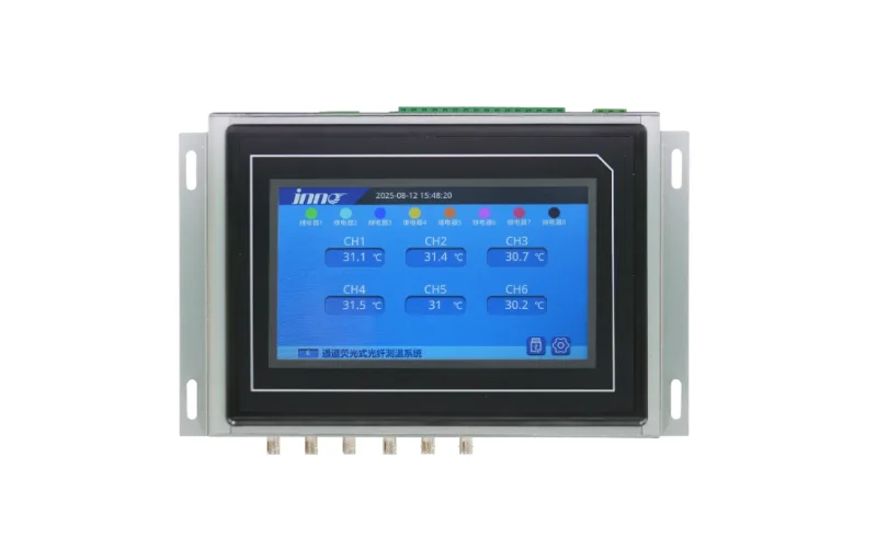
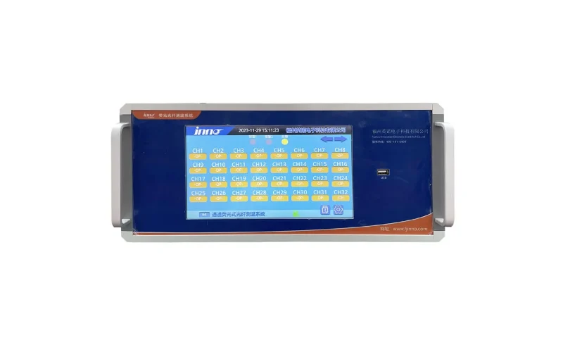
- Fiber optic probes for direct winding and hot spot measurement. They are suited to high-voltage, high-EMI environments because the probe and fiber are non-conductive. A fiber optic temperature measurement system for oil-immersed transformers combines in-winding probes, tank wall feedthroughs and a measurement unit.
- Resistance temperature detectors (RTDs) in thermowells for top-oil temperature and, in dry-type transformers, embedded in or near the windings.
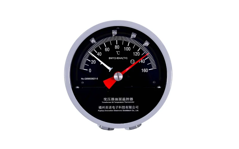
- Winding temperature indicators that estimate winding temperature from oil temperature and a current-dependent thermal image.
DGA Sensors and Monitors
- Single-gas or composite-gas sensors, often hydrogen-based or hydrogen-and-carbon-monoxide-based. They are used as early warning indicators.
- Multi-gas monitors using principles such as gas chromatography, photoacoustic spectroscopy or infrared absorption. They measure several individual gases and support fault-type interpretation.
Partial Discharge Sensors
- UHF sensors installed through oil drain valves or dielectric windows to detect electromagnetic signals from PD inside the tank.
- High-frequency current transformers (HFCTs) on grounding connections or at bushing taps.
- Acoustic emission sensors mounted on the tank wall, often used for locating the PD source.
Bushing Monitoring Sensors
- Test tap adapters that connect to the bushing measurement tap and let the monitoring unit measure leakage current and derive changes in capacitance and dissipation factor.
OLTC Monitoring Sensors
- Current or power transducers on the drive motor circuit.
- Tap position transmitters and operation counters.
- Temperature sensors for the OLTC compartment and main tank.
- Vibration or acoustic sensors for switching-sequence analysis, where used.
Oil Condition Sensors
- Moisture-in-oil sensors, typically capacitive thin-film types that report relative saturation or water activity together with oil temperature.
- Oil level gauges, gas-actuated relays and pressure sensors or devices for level, gas accumulation and pressure events.
How Does Online Transformer Condition Monitoring Work?
An online monitoring system is a data chain from the sensor to the operator. A typical architecture looks like this:
- Sensors are installed on or in the transformer: winding probes, oil temperature sensors, DGA and moisture sensors, PD sensors, bushing tap adapters and OLTC transducers.
- Data acquisition or monitoring devices receive the sensor signals. They provide signal conditioning, measurement and channel management, often in a cabinet near the transformer.
- Signal processing converts raw signals into engineering values and derived quantities. Examples include calculated hot spot temperature, gas concentrations and rates of change, PD magnitude and pattern data, and bushing capacitance and tan delta changes.
- Alarm and trend analysis compares values against configured alarm levels, records trends and events, and may generate local indications or relay contact outputs.
- Communication interfaces send data upstream. RS485 with Modbus is common for monitoring devices. Other interfaces depend on the specific device and should be confirmed with the supplier.
- SCADA or a centralized monitoring system collects data from one or more transformers or substations for operators, maintenance engineers and asset management teams.
Several design points matter in practice:
- Channel count and measurement points must be defined early, especially for in-winding fiber optic probes that are fixed during manufacture.
- Time synchronization and consistent tagging make it possible to correlate data from different devices, for example PD events with load changes or temperature with gas generation.
- Local versus central processing should be decided up front. Critical alarms usually need a local relay output, while detailed trend analysis can take place centrally.
- Data volume differs widely between parameters. Temperature and DGA data are modest, while PD raw data can be large. The communication design should reflect this.
Condition Monitoring Strategy by Transformer Type
Different transformer types have different dominant risks, so their monitoring priorities differ. The table below is a starting point, not a mandatory configuration. The actual scope should come from the asset's criticality and known issues.
| نوع المحول | Key Risks | Priority Monitoring Parameters | Typical Monitoring Approach |
|---|---|---|---|
| Power transformer | Insulation thermal aging, internal faults, bushing failure, OLTC problems, high consequence of failure | Hot spot and top-oil temperature, DGA, bushing condition, OLTC condition, moisture. PD for critical or suspect units. | Online monitoring of selected parameters combined with periodic oil sampling and offline electrical testing |
| Oil-immersed transformer (general, including distribution and industrial units) | Overheating, oil degradation, moisture, leaks, internal faults | Top-oil temperature, oil level, periodic DGA and oil quality. Online DGA or winding temperature for critical or heavily loaded units. | Mainly periodic inspection and oil sampling, with online monitoring added where criticality or loading justifies it |
| Dry-type transformer | Winding overheating, insulation deterioration, PD in resin or insulation systems, cooling fan failure | Winding temperature, cooling system status. PD where insulation condition is a concern. | Winding temperature monitoring with fan control and alarms, supplemented by periodic inspection and testing. DGA does not apply. |
| Substation transformer | Depends on rating. Often remote with limited site attendance, and an outage affects downstream supply. | Parameters based on rating and type. Temperature, DGA and bushing condition are common. OLTC where fitted. | Remote online monitoring integrated with substation SCADA, supported by scheduled site testing |
Large and critical units usually justify the widest monitoring scope. For application considerations specific to these assets, see power transformer monitoring.
How to Select a Transformer Condition Monitoring Strategy
A practical monitoring strategy starts from risk rather than from available technology. The following factors should guide selection:
- Transformer type and insulation system. Oil-immersed and dry-type transformers have different indicators. DGA and oil moisture apply only to liquid-filled units.
- Voltage and power rating. Higher-rated units usually have condenser bushings, OLTCs and larger consequences of failure, which widens the relevant parameter set.
- Asset criticality. Consider the impact of an unplanned outage, the availability of redundancy or a spare, and the replacement lead time.
- Known failure modes. The unit's history, fleet experience with the same design and results from past tests should shape priorities. Our guide to transformer failure modes maps common failures to detection methods.
- Operating and loading conditions. Heavily loaded, cyclically loaded or overload-prone transformers benefit more from accurate hot spot information.
- Required sensors and measurement points. Decide which parameters need direct measurement and which can rely on calculation or periodic testing.
- Number of channels. This includes winding probe count, number of bushings, number of PD sensors and any additional inputs.
- Communication requirements. Define the interfaces, protocols and data points needed at the substation and control center levels.
- Existing SCADA and monitoring systems. New devices should fit the existing architecture rather than create isolated systems.
- Alarm requirements. Decide which conditions need local relay outputs, which need SCADA alarms and which need only trend review.
- Installation and access limitations. In-winding sensors require installation during manufacture or rework. Some online sensors need valves, test taps or outage windows.
- Project budget. Align monitoring investment with the value of the asset and the cost of failure. Well-chosen monitoring on the most critical units is often more effective than minimal monitoring spread across all units.
How Should Transformer Monitoring Data Be Used?
Collecting data is only part of the task. Condition monitoring pays off when the data is interpreted consistently and linked to actions.
Baseline
Establish reference values after commissioning or after major maintenance, under known operating conditions. Each transformer has its own normal behavior, and later changes are judged against this baseline.
Trend
Long-term trends reveal gradual deterioration that single readings cannot show, such as slowly rising gas levels, changing bushing capacitance or increasing OLTC motor load.
Rate of Change
How fast a value changes is often more significant than its absolute level. A rapid increase in gas generation or PD activity usually calls for faster investigation than a stable but elevated value.
Multi-Parameter Correlation
Comparing parameters makes interpretation more reliable. Examples:
- Temperature rise should be evaluated against load and ambient conditions.
- Gas generation that follows temperature or load changes suggests a thermally related mechanism.
- PD activity together with hydrogen increase in DGA strengthens the evidence of an electrical insulation problem.
- Moisture readings should be interpreted together with oil temperature.
الإنذار
Alarm levels are commonly arranged in stages, for example an early caution level for review and a higher level for urgent action. There are no universal alarm thresholds that suit every transformer. Actual limits should be set from the transformer design and insulation system, manufacturer limits, applicable standards and utility or project requirements, and they should be reviewed as operating experience accumulates.
Maintenance Decision
Every alarm or significant trend should lead to a defined response. Examples include a confirmatory oil sample, a targeted offline test, a load adjustment, an inspection or planned maintenance. Without defined responses, monitoring data tends to be collected but not acted upon.
Transformer Condition Monitoring and SCADA Integration
Integrating condition data into SCADA or a centralized monitoring platform makes it available to operators and engineers without site visits. Common integration methods include:
- RS485 with Modbus. A widely used, straightforward way to transfer measured values, status and alarms from monitoring devices to SCADA, RTUs or gateways.
- Relay alarm outputs. Hardwired contacts for critical alarms. They provide a simple and robust signal path that does not depend on the communication network.
- Centralized monitoring. Data from multiple transformers and substations is collected in one system for fleet-level trending and asset management.
- Remote condition monitoring. Engineers can review trends and events remotely and decide whether a site visit or test is needed.
Before integration, define the register map or data point list, polling rates, alarm priorities and naming conventions. If the project requires a specific substation protocol or network interface, confirm that each monitoring device supports it rather than assuming compatibility.
When Is Online Transformer Condition Monitoring Most Useful?
Online monitoring is not equally justified for every transformer. It tends to provide the most value in the following situations:
- محولات الطاقة الحرجة, whose failure would interrupt important loads or grid operation.
- High-value assets with long replacement lead times and no readily available spare.
- Heavily loaded or overload-prone equipment, where accurate thermal information supports loading decisions.
- محطات التحويل عن بُعد أو غير المراقبة, where site inspections are infrequent.
- Transformers with developing abnormal trends, for example rising gases in periodic samples, where closer observation is needed until the cause is understood or resolved.
- Locations where manual inspection is difficult or hazardous.
- Applications where an unexpected outage has a high operational or financial impact, such as continuous industrial processes.
For less critical units, periodic inspection and oil sampling, sometimes combined with basic temperature monitoring, may be a reasonable and cost-effective approach.
Transformer Condition Monitoring Implementation Checklist
The following steps provide a practical sequence for planning and implementing a monitoring project:
- Identify the transformer type. Record the insulation system, rating, cooling method, and presence of an OLTC and condenser bushings.
- Identify critical failure modes. Use the unit's history, test results, fleet experience and design information.
- Select monitoring parameters. Choose the parameters that address the identified risks, and decide which will be monitored online and which through periodic testing.
- Select sensors and measurement points. Determine sensor types and locations, including whether in-winding probes must be specified at the manufacturing stage.
- Determine channel count. Count temperature probes, bushings, PD sensors and other inputs, and allow for future expansion where practical.
- Define communication and SCADA requirements. Specify interfaces, protocols, data points and integration responsibilities.
- Define alarm and trend strategy. Set alarm stages based on manufacturer limits, applicable standards and project requirements, and define the response to each alarm.
- Install and commission. Verify sensor installation, wiring, measurements and communication, and test alarm outputs end to end.
- Establish baseline data. Record reference values under known operating conditions after commissioning.
- Review trends periodically. Schedule regular data reviews, compare online results with periodic test results and adjust alarm levels and monitoring scope as needed.
الأسئلة الشائعة
ما المقصود بمراقبة حالة المحولات؟
Transformer condition monitoring is the continuous or periodic assessment of a transformer's thermal, chemical, electrical and mechanical indicators to determine its health, detect developing faults early and support condition-based maintenance decisions.
What parameters should be monitored in a transformer?
Common parameters include winding hot spot temperature, top-oil temperature, dissolved gases, partial discharge, bushing capacitance and dissipation factor, OLTC condition, oil moisture, oil level and pressure, and load current. The right selection depends on transformer type, criticality and known risks. Not every transformer needs all of them.
ما الفرق بين مراقبة المحولات ومراقبة حالة المحولات؟
Transformer monitoring often refers to measuring operating values such as temperature, load or tap position. Condition monitoring goes further: it interprets those values and diagnostic indicators over time, against a baseline and across multiple parameters, to judge the health of the transformer.
Is DGA required for every transformer?
No. DGA applies only to liquid-filled transformers. For those units, periodic laboratory DGA is widely used. Online DGA is usually reserved for critical, high-value or suspect transformers, where continuous gas trending justifies the investment.
What is the difference between online monitoring and periodic testing?
Online monitoring collects data continuously from installed sensors and shows trends and events between site visits. Periodic testing, such as oil sampling and offline electrical tests, provides detailed diagnostics at specific intervals. The two approaches complement each other, and online monitoring does not remove the need for periodic testing.
What sensors are used for transformer condition monitoring?
Typical sensors include fiber optic probes and RTDs for temperature, single-gas or multi-gas DGA monitors, UHF, HFCT and acoustic sensors for partial discharge, bushing test tap adapters, OLTC motor current and position transducers, moisture-in-oil sensors, and oil level and pressure devices.
Can transformer monitoring systems connect to SCADA?
Yes, in most cases. RS485 with Modbus and relay alarm outputs are common integration methods. Supported interfaces vary between devices, so confirm the required protocol and data points with the supplier during specification.
How do I choose which transformer parameters to monitor?
Start with the transformer type, its criticality and its most likely failure modes. Then select the parameters that best detect those failure modes, decide which should be monitored online and which through periodic testing, and account for installation constraints, SCADA requirements and budget.
Conclusion
Effective transformer condition monitoring is not about installing every available sensor. It means selecting the indicators that match the transformer's type, criticality and failure risks, and then using the data in a disciplined way through baselines, trends, correlation and defined maintenance responses. Online monitoring and periodic testing each have a role, and together they give a more reliable picture of transformer health than either can alone.
For system architecture and configuration options, see our transformer monitoring solutions.







