

كيف يمكن مراقبة درجة حرارة النقاط الساخنة في لفات محول الفرن؟
تاريخ النشر:23 أكتوبر 2026 الساعة 14:57:45
- Furnace transformer hot-spot monitoring should focus on winding temperature under high-current and cyclic loading, not only on tank or top-oil readings.
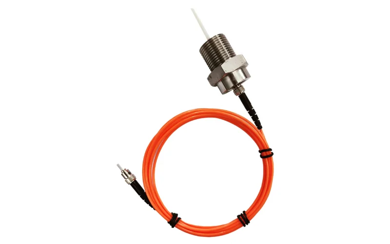
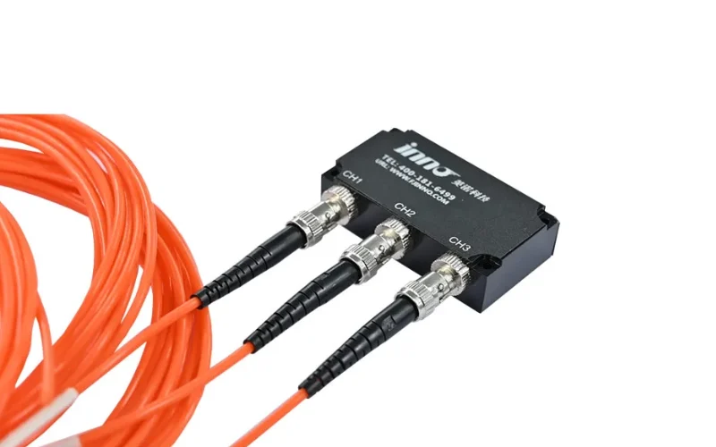
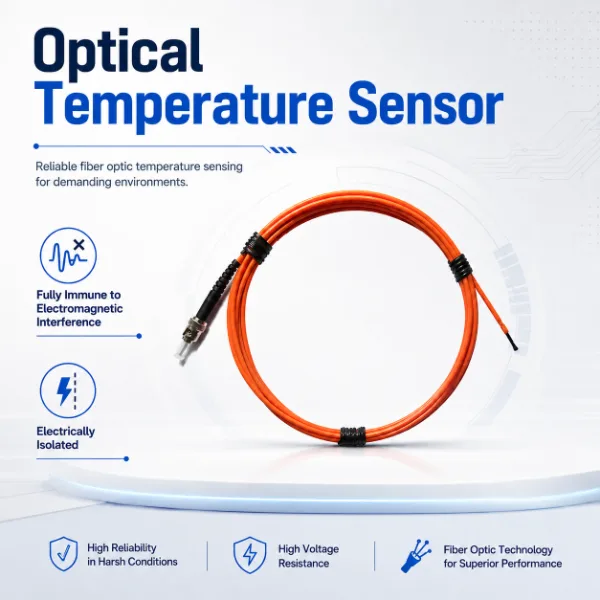
- Fiber optic sensors measure temperature directly at selected winding hot-spot locations. Each reading represents the probe position.
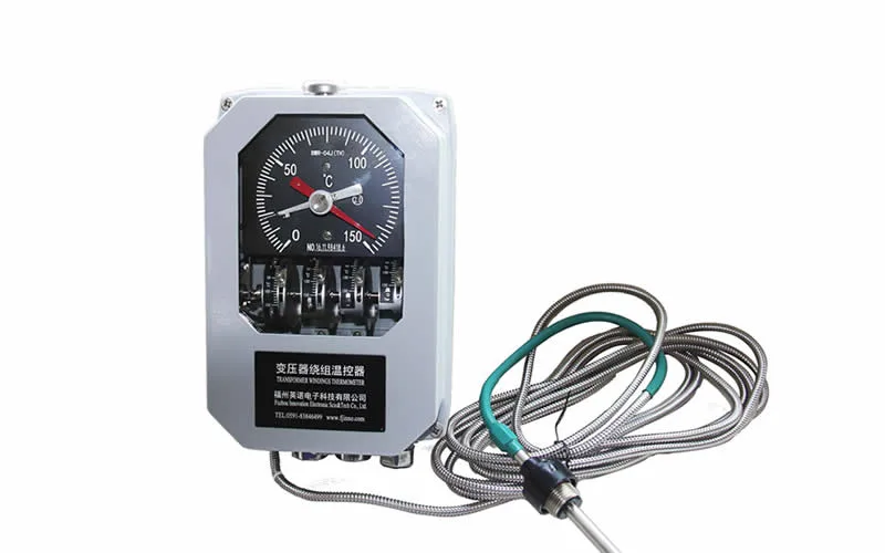
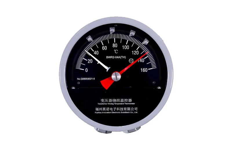
- PT100 sensors suit accessible temperature points such as oil, dry-type windings or other electrically suitable locations, depending on transformer design.
- Fiber optic sensing is preferred for direct measurement inside high-voltage windings because it is electrically isolated and immune to EMI.
- Evaluate temperature trends together with load and cooling condition.
جدول المحتويات
- 1. Why Hot-Spot Temperature Matters in Furnace Transformers
- 2. Fiber Optic vs PT100 Temperature Measurement
- 3. Direct Winding Hot-Spot Monitoring with Fiber Optic Sensors
- 4. Where PT100 Sensors Can Be Used
- 5. Temperature, Load and Cooling Trend Analysis
- 6. Furnace Transformer Temperature Monitoring Checklist
- 7. Furnace Transformer Temperature Monitoring FAQ
1. Why Hot-Spot Temperature Matters in Furnace Transformers
High secondary current, rapid load swings, harmonics and repeated heavy-load cycles heat the windings unevenly. Cooling demand is high, and the winding goes through thermal cycling many times a day.
Top-oil temperature responds slowly because winding heat must first transfer into the oil. A local winding hot spot can show thermal stress earlier, and at a different magnitude, than a general oil reading.
The monitoring questions are where the hot spot is likely to sit, how fast it responds to load steps, and whether cooling follows. Alarm limits depend on the insulation system and manufacturer design, so they should come from the transformer specification rather than a generic value.
2. Fiber Optic vs PT100 Temperature Measurement
The two methods answer different measurement questions, so they are usually complementary rather than interchangeable.
| طريقة القياس | Typical Measurement Point | العزل الكهربائي | مقاومة التداخل الكهرومغناطيسي | قياس نقاط التسخين في اللف المباشر | الاستخدام النموذجي |
|---|---|---|---|---|---|
| مستشعر الألياف الضوئية | Selected locations inside or at the winding | Yes, electrically insulating sensing path | Immune, optical signal | Yes, at the installed probe position | Hot-spot monitoring in high-voltage windings |
| PT100 / RTD | Oil, dry-type windings, core, enclosure or other designed sensor positions | Depends on sensor construction and insulation design | Depends on shielding and signal conditioning | Yes at electrically suitable locations such as dry-type windings; not typical inside high-voltage oil-immersed windings | Oil, cooling and auxiliary temperature points |
PT100 can be used at electrically suitable and accessible measurement locations, including oil, dry-type transformer windings or other designed sensor positions. Fiber optic sensors are better suited to direct measurement inside high-voltage winding environments because the sensing path is electrically insulating and immune to electromagnetic interference. Many installations combine both: fiber optic probes at winding hot spots and PT100 at oil and auxiliary points.
3. Direct Winding Hot-Spot Monitoring with Fiber Optic Sensors
Fiber optic probes are installed at selected winding locations, normally during manufacture or major overhaul when the winding is accessible. The transmitter reports the temperature at the probe position, not an estimate derived from oil temperature and load. Unlike a calculated value, a probe reading is tied to a physical location, which is why winding hot-spot temperature measurement depends on correct probe placement.
The fiber carries light, not an electrical signal. There is no conductive path from the winding to the instrument, and readings are not disturbed by high-current switching or strong fields.
3.1 Channels, Alarms and Communication
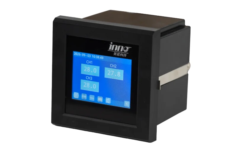
Multi-channel instruments track several locations, for example one probe per phase on the high-voltage winding plus additional probes on the low-voltage winding or at other heights. Depending on the instrument, the data supports local display, alarm relays and communication to SCADA. A probe only measures where it is placed, so probe count and position should follow the thermal design.
3.2 Reference Specifications
For reference, the IF-TF نظام قياس درجة الحرارة بالألياف الضوئية للمحولات المغمورة بالزيت lists the values below. They apply to that configuration only.
| المواصفات | INNOFZ Fiber Optic Temperature Monitoring System |
|---|---|
| القنوات | 1–18 (customizable) |
| نطاق درجات الحرارة | من −40 درجة مئوية إلى +260 درجة مئوية (يمكن تخصيص نطاق أعلى) |
| الدقة | ±1 درجة مئوية (يمكن تخصيص دقة أعلى) |
| القرار | 0.1 درجة مئوية |
| التواصل | RS485 / Modbus-RTU; 4–20 mA analog output |
| مخرج الإنذار | Relay outputs for fan start, alarm and trip, configurable per channel |
| مصدر الطاقة | تيار متردد/تيار مستمر 220 فولت |
| نوع المجس | Fluorescent quartz fiber probe, 100 kV all-dielectric, oil-resistant, 2.5 mm diameter |
4. Where PT100 Sensors Can Be Used
PT100 and other RTD sensors are well suited to:
- درجة حرارة الزيت القصوى
- accessible winding locations in dry-type transformers
- core, enclosure or structural temperature where design permits
- cooling-related temperature measurement, such as cooler inlet and outlet
An RTD outputs resistance, so lead-wire arrangement (2-, 3- or 4-wire), shielding and signal conditioning affect accuracy. Ordinary PT100 sensors are not intended for placement inside high-voltage oil-immersed windings, where insulation and EMI become design constraints.
5. Temperature, Load and Cooling Trend Analysis
One temperature value is not enough. Read winding temperature, oil temperature, transformer current, ambient temperature, cooling fan status, pump status and temperature rise trend together.
| Observed Pattern | Possible Interpretation |
|---|---|
| Stable load + rising winding temperature | May indicate reduced cooling or developing thermal abnormality |
| Cooling starts + temperature does not decrease | Cooling performance should be checked |
| High load + predictable temperature rise | May reflect expected thermal response |
| Winding temperature rises while top-oil temperature stays flat | Can suggest local heating or limited oil flow near the winding; requires verification |
A حل لمراقبة درجة حرارة المحولات can bring these signals into one view. Compare each reading with earlier cycles at the same load and cooling state. A baseline is more informative than a single threshold.
6. Furnace Transformer Temperature Monitoring Checklist
| Check Item | What to Monitor |
|---|---|
| منطقة ساخنة متعرجة | Probe temperature by phase and winding location |
| درجة حرارة الزيت القصوى | Oil temperature level and trend |
| Load / current | Current, load steps and heavy-load duty cycle |
| Cooling fan | Run status, start events and temperature response after start |
| Oil pump | Run status and temperature response during circulation |
| درجة الحرارة المحيطة | Surrounding temperature affecting cooling capacity |
| Alarm history | Alarm events, duration and load state at the time |
| Temperature trend | Temperature rise per heavy-load cycle compared with earlier cycles |
7. Furnace Transformer Temperature Monitoring FAQ
7.1 How is furnace transformer winding temperature monitored?
Winding temperature is monitored with direct probes at selected hot-spot locations, usually fiber optic sensors in high-voltage windings. These are combined with top-oil measurement, often by PT100, plus load and cooling data. Comparing trends against load and cooling status shows whether thermal behavior is changing.
7.2 Is fiber optic sensing better than PT100 for winding hot spots?
For direct measurement inside high-voltage windings, fiber optic sensing is the better fit because its sensing path is electrically insulating and immune to EMI. PT100 is not inferior in general. It works well in oil, dry-type windings and other accessible, electrically suitable positions.
7.3 Can PT100 measure furnace transformer temperature?
Yes. PT100 sensors can measure top-oil temperature, dry-type winding temperature, core or enclosure temperature and cooling-related points where the design permits. They are not normally placed directly inside high-voltage oil-immersed windings, where fiber optic probes are used.
7.4 Why does furnace transformer winding temperature rise rapidly?
High current and fast load changes raise winding losses almost immediately, while oil and cooling circuits respond more slowly. Harmonics can add local heating. Winding temperature therefore rises quickly relative to oil temperature, so load current and cooling status should be read alongside it.