OLTC-Transformatorüberwachung: Was bei einem Laststufenschalter zu überwachen ist
Veröffentlichungsdatum:28. September 2026, 09:42:44 Uhr
- Die on-load tap changer (OLTC) is the only major moving part inside a power transformer, and international reliability surveys such as CIGRE Technical Brochure 642 rank it among the leading failure locations in substation transformers.
- Effective OLTC monitoring tracks mechanical health (motor drive current, torque, switching time, vibro-acoustic signature), thermal health (compartment oil temperature vs. main tank temperature) and oil health (dissolved gases, moisture, dielectric strength, oil level).
- Tap position, operation count and cumulative switched current let you move from fixed calendar maintenance to condition-based maintenance tied to real contact wear.
- DGA of OLTC oil must be read differently from main tank DGA: acetylene is normal in arcing-in-oil diverter switches, so the trend and the gas ratios matter more than absolute values (see IEEE C57.139).
- A rising differential temperature between the OLTC compartment and the main tank is one of the earliest, cheapest indicators of contact coking and overheating.
- The most useful results come from combining an OLTC-Online-Überwachungssystem with main tank DGA, winding hot-spot temperature, bushing and partial discharge data in one platform.
- A practical parameter table, alarm-setting guidance, a field checklist and 10 FAQs are included below.
Inhaltsverzeichnis
- What an On-Load Tap Changer Does and How It Fails
- Why OLTC Monitoring Matters
- Motor Drive Current, Torque and Power
- Switching Time and Vibro-Acoustic Signature
- OLTC Oil Temperature and Differential Temperature
- Dissolved Gas Analysis of OLTC Oil
- Oil Quality, Moisture and Oil Level
- Tap Position, Operation Count and Contact Wear
- Protective Devices, Voltage Regulation and Auxiliary Circuits
- OLTC Monitoring Parameter Summary Table
- Building an OLTC Monitoring System
- Setting Alarm Thresholds and Interpreting Trends
- Field Checklist for OLTC Monitoring Projects
- Häufig gestellte Fragen
1. What an On-Load Tap Changer Does and How It Fails
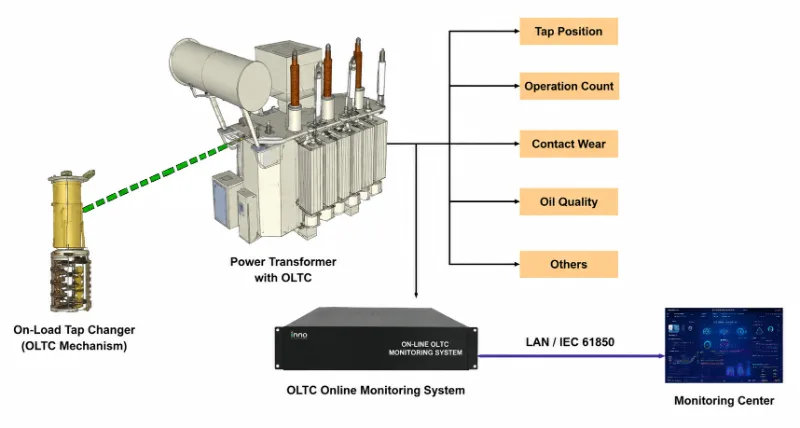
Ein on-load tap changer adjusts the turns ratio of a transformer while it carries load, keeping the output voltage inside the limits the network needs. In North America you will usually hear it called a load tap changer (LTC); IEC documents and most of the rest of the world use OLTC. Either way, it is the component that works hardest mechanically: a transmission or distribution transformer on automatic voltage control can make anywhere from a handful to several dozen tap changes per day.
Because it moves, switches load current and interrupts arcs, the OLTC wears out in ways the static parts of a transformer do not. That is exactly why it deserves its own monitoring strategy rather than being lumped in with general Überwachung von Leistungstransformatoren.
1.1 Main OLTC Components
- Tap selector – pre-selects the next tap without carrying switching current.
- Diverter switch – transfers the load current from one tap to the next, usually through transition resistors, in a few tens of milliseconds.
- Transition resistors (or reactors) – limit circulating current while both taps are briefly bridged.
- Motor drive unit (MDU) – the cabinet on the tank wall with the motor, gearbox, spring energy accumulator, position indicator, limit switches and control circuits.
- Drive shafts and bevel gears – transmit motion from the MDU to the tap changer head.
- OLTC compartment and conservator – a separate oil volume (for compartment-type designs) with its own breather, oil level gauge, protective relay and pressure relief device.
1.2 Common OLTC Designs
1.2.1 Arcing-in-Oil Diverter Switch
The classic design. The diverter switch breaks current in oil, which produces carbon, degrades the oil and erodes the contacts. Maintenance intervals are typically driven by operation count and oil condition.
1.2.2 Vacuum-Type OLTC
Switching arcs are confined inside vacuum interrupters, so the surrounding oil stays much cleaner and contact wear is far lower. Mechanical monitoring still matters, but oil-based indicators behave very differently.
1.2.3 Selector-Switch (In-Tank) OLTC
Common on smaller transformers, the selector switch combines tap selection and switching. Some designs sit directly in the main tank oil, which makes main tank DGA interpretation harder because switching gases mix with the transformer oil.
1.3 Typical OLTC Failure Modes
- Contact wear, pitting and coking leading to high contact resistance and overheating.
- Carbonized, wet or contaminated oil reducing dielectric strength.
- Broken or weakened springs in the energy accumulator, causing slow or incomplete transitions.
- Failed or burned transition resistors after an interrupted operation.
- Drive shaft misalignment, worn gears and binding linkages.
- Motor drive faults: failed contactors, limit switches, heaters or control relays.
- Oil leakage between the OLTC compartment and the main tank.
- Out-of-step tap positions between phases or between paralleled transformers.
2. Why OLTC Monitoring Matters
CIGRE's international transformer reliability survey (Technical Brochure 642) identified tap changers as one of the most frequent failure locations in substation transformers, alongside windings and bushings. Many OLTC failures are mechanical and develop over weeks or months, which gives a monitoring system time to catch them if it is watching the right parameters.
From an asset manager's point of view, OLTC monitoring pays off in three ways:
- Avoiding catastrophic failures. A diverter switch that stops mid-transition can burn the transition resistors within seconds and may escalate to a tank rupture or fire.
- Replacing calendar-based maintenance. Opening a tap changer that is in good condition costs outage time, crew hours and adds the risk of reassembly errors. Condition data tells you when an intervention is actually needed.
- Protecting the whole transformer. OLTC problems show up as abnormal gases, temperature and pressure that can be confused with main tank faults. Monitoring both sides makes diagnosis far more reliable.
For the broader picture of how OLTC data fits alongside other parameters, see our guide to Methoden und Strategien zur Zustandsüberwachung von Transformatoren.
3. Motor Drive Current, Torque and Power
Motor current and power during each tap change are the backbone of mechanical OLTC monitoring. The drive motor has to overcome friction in the drive train, charge the spring accumulator and move the tap selector. Any change in that mechanical load shows up in the motor's electrical signature.
3.1 What the Motor Signature Reveals
- Higher peak or average power – binding linkages, worn bearings, poor lubrication, cold or thickened oil, misaligned shafts.
- Lower than normal power – broken coupling, slipping components, a spring that no longer charges fully.
- Longer run time – mechanical resistance or a sticking limit switch.
- Irregular shape of the curve – intermittent friction, damaged gear teeth or a loose part.
3.2 How It Is Measured
Current transformers and a voltage tap on the motor supply inside the motor drive cabinet feed a monitoring module that records the full power curve for every operation, typically sampled at hundreds of samples per second or more. Each new curve is compared with a baseline "fingerprint" recorded when the tap changer is known to be healthy, and separate baselines are usually kept for raise and lower operations and for different ambient temperatures.
3.2.1 Temperature Compensation
Oil viscosity changes strongly with temperature, so a tap changer operating at -20 °C draws noticeably more power than it does at 40 °C. A good OLTC-Online-Überwachungssystem correlates motor power with OLTC oil temperature so winter mornings do not trigger false alarms.
4. Switching Time and Vibro-Acoustic Signature
The diverter switch transition happens in tens of milliseconds, far too fast for motor current alone to describe. Vibro-acoustic monitoring fills that gap.
4.1 Vibration Sensors on the Tank
An accelerometer mounted on the tap changer head or on the tank wall near the OLTC records the sequence of mechanical impacts during each operation: the tap selector movement, the spring release and the individual contact transitions in the diverter switch. Compared against a reference signature, the timing and energy of those events reveal:
- Delayed or slowed contact transitions due to spring fatigue.
- Worn or loosened contacts that change the impact pattern.
- Missing events, suggesting a transition did not complete normally.
- Additional events, indicating contact bounce or loose parts.
4.2 Transition Time and Dynamic Resistance
Offline dynamic resistance measurement (DRM) during outages remains the reference test for transition timing and resistor condition. Online vibro-acoustic data does not replace it, but it tells you which units actually need the offline test first. In practice, most utilities use online monitoring to prioritize and DRM plus inspection to confirm.
5. OLTC Oil Temperature and Differential Temperature
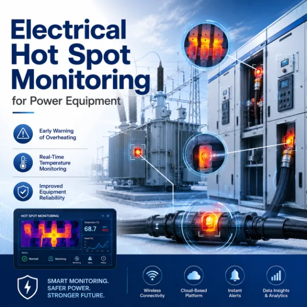
Temperature is the simplest, most robust indicator of electrical contact problems in a compartment-type OLTC. It is also one of the most underused.
5.1 The Differential Temperature Principle
In a separate OLTC compartment, there is little internal heat generation under normal conditions. The compartment oil is warmed mainly by the adjacent main tank, so it normally runs cooler than the main tank top oil. When contacts start to coke and contact resistance rises, I²R heating inside the compartment increases, and the gap closes. Eventually the OLTC oil can run hotter than the main tank.
Tracking the differential temperature (OLTC oil minus main tank top oil), rather than the absolute value, removes the effect of load and ambient swings. A slow upward drift in that differential over weeks is a classic early warning of contact deterioration, and many utilities begin investigating once the OLTC compartment becomes persistently warmer than the main tank.
5.2 Sensors for OLTC Temperature
5.2.1 Main Tank Top-Oil Temperature
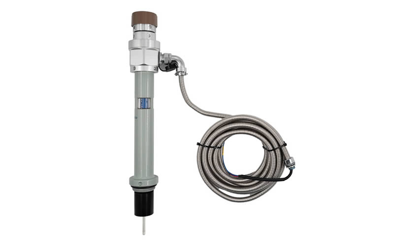
The reference side of the differential usually comes from the transformer's own Temperaturanzeige für Transformatoröl, such as the BWY-802/803A Öltemperaturanzeige or the BWY2-Öltemperaturanzeige, both of which provide a 4–20 mA output suitable for a monitoring system. The System zur Überwachung von Temperatur, Füllstand und Druck von Transformatoröl can capture top-oil, oil level and pressure in one package.
5.2.2 OLTC Compartment Temperature
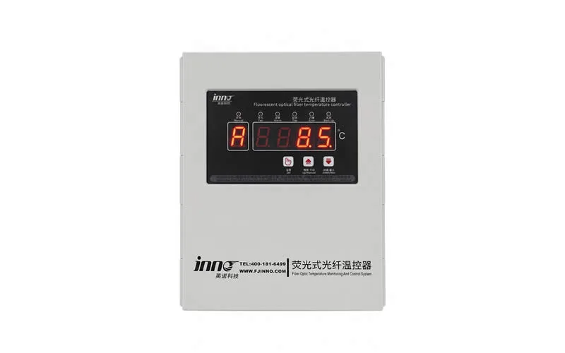
A PT100 RTD in a thermowell or a magnetic-mount surface sensor on the compartment wall is common on retrofits. Where a sensor needs to sit directly in energized oil, a Fluoreszierender Glasfaser-Temperatursensor offers full electrical isolation and immunity to electromagnetic interference. Our Fluoreszierende Glasfaser-Temperatursensoren und armored fiber optic sensors for oil-immersed transformers are built for exactly this kind of oil-immersed, high-voltage environment.
5.2.3 Winding Hot-Spot Context
Direct winding hot-spot measurement with a fiber optic winding temperature sensor helps separate real OLTC heating from overall transformer overloading. More on this in our article on winding hot-spot temperature measurement and on the transformer winding hot-spot monitoring application page.
6. Dissolved Gas Analysis of OLTC Oil
DGA is well established for main tank oil, but applying main tank rules to OLTC oil leads to wrong conclusions. The key reference here is IEEE C57.139, the IEEE guide for dissolved gas analysis in transformer load tap changers.
6.1 Why OLTC DGA Is Different
In an arcing-in-oil diverter switch, every operation produces arcing, so acetylene (C₂H₂) and hydrogen (H₂) are expected in normal service. High absolute acetylene alone therefore says little. What matters is:
- The ratio of heating gases to arcing gases. As contacts coke and overheat, ethylene (C₂H₄), and to a lesser degree methane and ethane, rise faster than acetylene. A rising C₂H₄/C₂H₂ ratio points to abnormal thermal activity.
- Rate of change relative to the number of operations since the last oil change or filtration.
- OLTC design. In a vacuum OLTC, significant acetylene is not normal and suggests a vacuum interrupter or bypass contact problem.
6.2 Watching for Leaks into the Main Tank
A leak through the barrier between the OLTC compartment and the main tank lets arcing gases migrate into the transformer oil. A sudden appearance of acetylene in main tank DGA, with a gas pattern similar to the OLTC oil and no other abnormal indicators, is a classic sign. Running an online DGA monitor on the main tank helps catch this early. See our online dissolved gas analysis monitoring system, the overview of Online-DGA-Überwachung von Transformatoren, and the comparison of online DGA vs. oil sampling.
6.3 Sampling Practice
For most OLTCs, periodic laboratory DGA remains the norm, with online gas sensors reserved for critical units. Take samples at a consistent point in the operating cycle, record the operation count at each sample, and always compare against the same unit's history rather than generic limits. Our Lösungen zur Analyse von gelöstem Gas page covers both approaches.
7. Oil Quality, Moisture and Oil Level
OLTC oil is the insulating and arc-quenching medium for the diverter switch. Carbon particles and moisture lower its dielectric strength, and a flashover inside the compartment can be severe.
7.1 Moisture
Online moisture-in-oil sensors report relative saturation and water content. Wet oil combined with carbon particles is particularly dangerous. Check the OLTC conservator breather regularly; a saturated silica gel breather is one of the most common and most avoidable causes of wet OLTC oil.
7.2 Dielectric Breakdown Voltage and Particles
Breakdown voltage (per IEC 60156 or ASTM D1816) is still a laboratory measurement for most operators. Many arcing-in-oil OLTCs are fitted with an online oil filtration unit that removes carbon and moisture continuously; monitoring its filter pressure drop and run status is part of OLTC monitoring too.
7.3 Oil Level and Pressure
Low OLTC oil level can expose live parts and indicates either a leak to atmosphere or a leak into the main tank. A rising OLTC oil level with a falling main tank level (or vice versa) is a strong indicator of an internal barrier leak. Level and pressure signals from the OLTC conservator should be logged alongside main tank values.
8. Tap Position, Operation Count and Contact Wear
8.1 Tap Position
Tap position is usually available from a resistor chain, BCD contacts or a position transmitter in the motor drive. Monitoring it continuously lets you:
- Confirm every operation actually reached the commanded position.
- Detect out-of-step conditions in parallel transformer banks.
- Correlate tap position with load, voltage and temperature.
- Spot "hunting" where the voltage regulator raises and lowers repeatedly.
8.2 Operation Counter
Every OLTC manufacturer specifies inspection and contact replacement intervals in terms of operations and years. A reliable electronic count, logged with time stamps, replaces manual counter readings and makes the maintenance plan accurate.
8.3 Cumulative Switched Current and Contact Wear Models
Contact erosion depends on the current switched, not just the number of operations. A tap changer on a heavily loaded unit wears much faster than an identical one on a lightly loaded unit. By recording load current at each operation and accumulating a wear value (typically based on I or I² per operation, according to the manufacturer's model), the monitoring system estimates remaining contact life and flags when an inspection is due.
8.4 Tap Change Frequency
An unexpected jump in daily operations often points to a voltage regulation problem, a changed network configuration or an AVR setting that is too tight. Addressing that reduces wear without touching the tap changer itself.
9. Protective Devices, Voltage Regulation and Auxiliary Circuits
9.1 Protective Relay and Pressure Relief
The OLTC protective relay (an oil-surge or oil-flow relay) trips the transformer on a sudden oil surge from the compartment. Pressure relief devices and, on some designs, rupture discs protect the compartment against overpressure. Monitoring the status and trip history of these devices, including the time stamp relative to the last tap operation, is essential for post-event analysis.
9.2 Automatic Voltage Regulator (ANSI 90)
The voltage regulating relay decides when the OLTC operates. Logging its set point, bandwidth, time delay and raise/lower commands alongside tap position explains why the tap changer operated and helps separate control problems from mechanical ones.
9.3 Motor Drive Cabinet Environment
- Heater and thermostat status – condensation in the cabinet causes corrosion and control failures.
- Cabinet humidity and temperature.
- Auxiliary supply voltage and motor protection breaker status.
- Limit switch and step-by-step contact operation.
- Door switch for security and maintenance logging.
10. OLTC Monitoring Parameter Summary Table
| Parameter | Typical Sensor | What It Detects | Priorität |
|---|---|---|---|
| Motor current / power | CTs and VT tap in motor drive cabinet | Binding, lubrication issues, spring problems, drive train wear | Hoch |
| Motor run time | Monitoring module timer | Mechanical resistance, limit switch faults | Hoch |
| Vibro-acoustic signature | Accelerometer on OLTC head or tank | Contact wear, spring fatigue, incomplete transitions | Medium–High |
| OLTC oil temperature | PT100, surface sensor or fiber optic probe | Contact coking and overheating | Hoch |
| Main tank top-oil temperature | Oil temperature indicator (4–20 mA) | Reference for differential temperature | Hoch |
| Differential temperature | Berechnet | Early thermal fault inside OLTC compartment | Hoch |
| Dissolved gases in OLTC oil | Lab DGA or online gas sensor | Abnormal heating vs. normal arcing | Medium–High |
| Main tank DGA | Online-DGA-Monitor | OLTC barrier leak, main tank faults | Hoch |
| Moisture in OLTC oil | Kapazitiver Feuchtigkeitssensor | Wet oil, breather failure | Mittel |
| OLTC oil level / pressure | Level gauge contacts, pressure transmitter | Leaks to atmosphere or main tank | Mittel |
| Tap position | Position transmitter, BCD contacts | Incomplete operations, out-of-step, hunting | Hoch |
| Operation count and switched current | Counter plus load current | Contact wear, maintenance scheduling | Hoch |
| Protective relay / PRD status | Auxiliary contacts | Internal faults, event correlation | Hoch |
| Cabinet heater and humidity | Status contact, humidity sensor | Condensation and corrosion risk | Low–Medium |
11. Building an OLTC Monitoring System
11.1 Field Layer
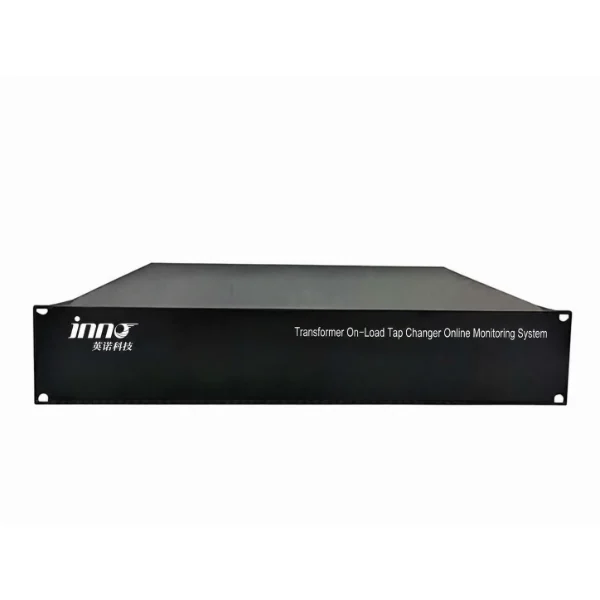
Sensors in and around the motor drive cabinet, on the tank and in the oil connect to an IED or data acquisition unit mounted on or near the transformer. This unit captures high-speed data during each tap change (motor power and vibration) and slower trend data (temperatures, gases, moisture, levels) continuously. Our OLTC-Online-Überwachungssystem für Transformatoren is designed around this approach.
11.2 Integration with Other Transformer Monitoring
OLTC data is most valuable when it sits next to the rest of the transformer's condition data. A typical integrated setup includes:
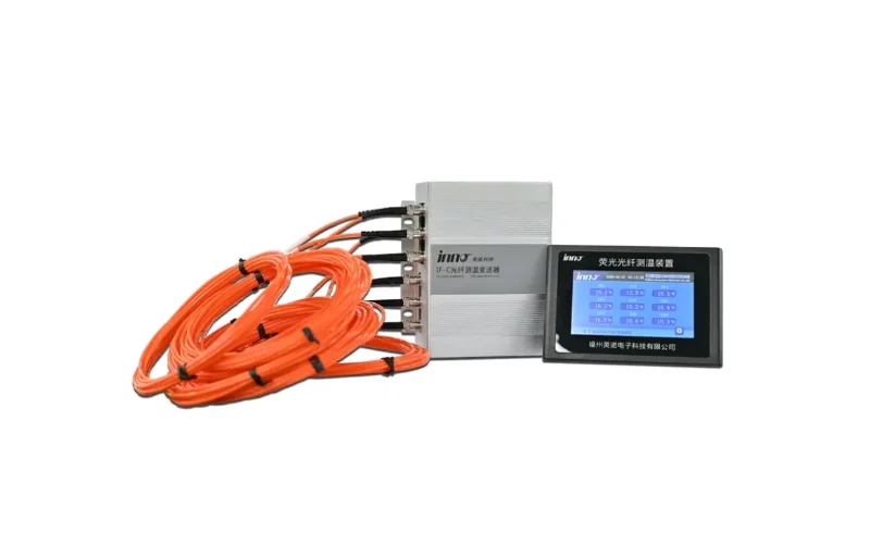
- A Mehrkanal-Temperaturüberwachungssystem mit Glasfasertechnik for winding hot spots, such as the Mehrkanal-Glasfaser-Temperaturmesssystem or the fiber optic temperature system for oil-immersed transformers.
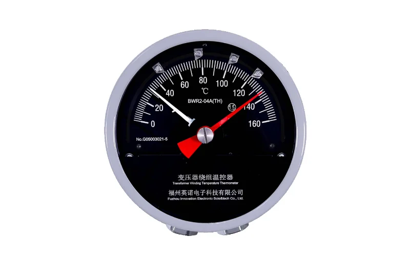
- A Anzeige der Wicklungstemperatur like the BWR-04/06AJTH Wicklungstemperaturanzeige for the classic thermal image reading and cooling control.
- Ein online DGA monitor for main tank oil.
- A Buchsenüberwachungssystem – see the Überwachungssystem für Transformator-Durchführungen and our article on Überwachung von Transformator-Durchführungen.
- A partial discharge monitoring system – see the Online-Überwachungssystem für Teilentladungen an Transformatoren und unser Leitfaden zu Überwachung von Teilentladungen in Transformatoren.
11.3 Communication and SCADA
Most utilities expect IEC 61850 for new substations, with DNP3 and Modbus RTU/TCP still widely used on retrofits. Event records (motor power curves, vibration traces) should be stored locally and retrievable remotely, while trend values and alarms go to SCADA or an asset management platform.
11.4 Retrofit vs. New Transformers
11.4.1 New Units
Specify OLTC monitoring at the order stage. The manufacturer can fit sensors, thermowells and position transmitters in the factory and record baseline signatures during factory acceptance testing.
11.4.2 Retrofits
Most OLTC monitoring can be added without an outage: motor current CTs, cabinet sensors, surface-mounted accelerometers and temperature sensors are external. Oil sensors may need a valve connection. Baselines should be recorded soon after the most recent OLTC maintenance, when the condition is known.
Our transformer OLTC monitoring solutions page and the wider Lösungen zur Transformatorüberwachung overview explain how these pieces fit together for different fleets.
12. Setting Alarm Thresholds and Interpreting Trends
12.1 Start from the Unit's Own Baseline
Generic limits are a starting point, not an answer. Every tap changer has its own normal motor power, vibration pattern, temperature differential and gas profile. Record at least several weeks of data across a range of loads and temperatures before tightening alarm limits.
12.2 Two-Level Alarms
- Warning – deviation from baseline or trend change that deserves a closer look at the next opportunity.
- Alarm – a level or rate of change that justifies an inspection or restricting tap operations.
12.3 Correlate Before You Act
A single abnormal reading rarely justifies an outage. Confidence grows when independent indicators agree, for example a rising temperature differential together with increasing ethylene in OLTC oil, or a change in motor power together with a changed vibration signature. Cross-checking also filters out sensor faults and wiring issues.
12.4 Keep the Maintenance Loop Closed
After every inspection, record what was found and reset baselines where parts were replaced. Over time this creates a fleet-level understanding of which signatures actually precede which defects, which is where most of the long-term value of monitoring comes from.
13. Field Checklist for OLTC Monitoring Projects
- Confirm OLTC type (arcing-in-oil, vacuum, selector switch, in-tank or compartment) and manufacturer maintenance criteria.
- Collect maintenance history, last inspection date, operation count and past DGA results.
- Check the OLTC conservator breather, oil level and protective relay wiring before installing anything.
- Choose sensors: motor power, OLTC and main tank oil temperature, tap position and operation count as a minimum; vibration, OLTC DGA and moisture for critical units.
- Verify auxiliary supply, cabinet space, heater operation and cable routing.
- Plan communication (IEC 61850, DNP3 or Modbus) and data ownership with the SCADA and asset management teams.
- Record baselines after commissioning and after every maintenance intervention.
- Agree who reviews alarms, how quickly, and what action each alarm level triggers.
- Review trends at least quarterly for the first year and adjust thresholds based on real data.
We have deployed monitoring across Stromnetzbetreiber, Stromerzeugung, erneuerbare Energien sites, rail transit und Öl und Gas facilities, as well as Überwachung von Transformatoren in Umspannwerken projects. Our quality system and product approvals are listed on the certificates page. If you need help specifying an OLTC monitoring package for a particular transformer, our engineers are available through Technischer Support or the contact page.
14. Frequently Asked Questions
1. What is the most important parameter to monitor on an OLTC?
There is no single parameter that covers every failure mode. If you can only fit a few sensors, motor drive power, the differential temperature between OLTC oil and main tank oil, tap position and operation count give the best coverage of both mechanical and thermal problems for the cost.
2. What is the difference between an OLTC and an LTC?
They are the same device. "On-load tap changer" (OLTC) is the IEC term used in most countries, while "load tap changer" (LTC) is the common North American term used in IEEE standards such as IEEE C57.131.
3. Is acetylene in OLTC oil a sign of a fault?
Not necessarily. In an arcing-in-oil diverter switch, acetylene is produced during every normal operation. What matters is the trend, the ratio of heating gases (especially ethylene) to acetylene, and the OLTC design. In a vacuum-type OLTC, significant acetylene is abnormal.
4. Why should the OLTC compartment normally be cooler than the main tank?
In a separate compartment, the OLTC generates very little heat under normal conditions, so its oil is mainly warmed by the neighboring main tank. When contacts deteriorate, extra resistive heating raises the compartment temperature. A differential that trends upward is an early warning.
5. Can OLTC monitoring be retrofitted without an outage?
In most cases, yes. Motor current sensors, cabinet sensors, surface-mounted temperature sensors and accelerometers are external. Oil-connected sensors may need an existing valve, and some installations may need a short outage depending on the design and local safety rules.
6. How often should an OLTC be inspected?
Follow the manufacturer's criteria, which are usually based on the number of operations and elapsed years. Vacuum-type OLTCs typically allow many more operations between inspections than arcing-in-oil designs. Monitoring data helps you inspect when condition requires it rather than purely on the calendar.
7. Which standards apply to OLTC monitoring?
Key references include IEC 60214-1 and IEC 60214-2 for tap changer requirements and application, IEEE C57.131 for tap changer requirements, IEEE C57.139 for DGA in load tap changers, IEEE C57.143 for monitoring equipment on liquid-immersed transformers, and CIGRE brochures on tap changer maintenance and transformer reliability.
8. Can fiber optic sensors be used in an OLTC?
Yes. Fluorescent fiber optic temperature sensors are fully dielectric and immune to electromagnetic interference, which makes them suitable for oil-immersed, high-voltage locations. For most OLTC temperature monitoring, a probe in the compartment oil or on the compartment wall is sufficient.
9. How can I tell if OLTC oil is leaking into the main tank?
Typical signs are a sudden appearance of acetylene in main tank DGA with no other abnormal indicators, a gas pattern in the main tank resembling the OLTC oil, and opposite changes in oil level between the OLTC conservator and the main conservator.
10. Does OLTC monitoring replace offline tests like dynamic resistance measurement?
No. Online monitoring tells you which tap changers need attention and when. Offline tests such as dynamic resistance measurement, winding resistance and internal inspection remain the way to confirm a diagnosis and verify repairs.