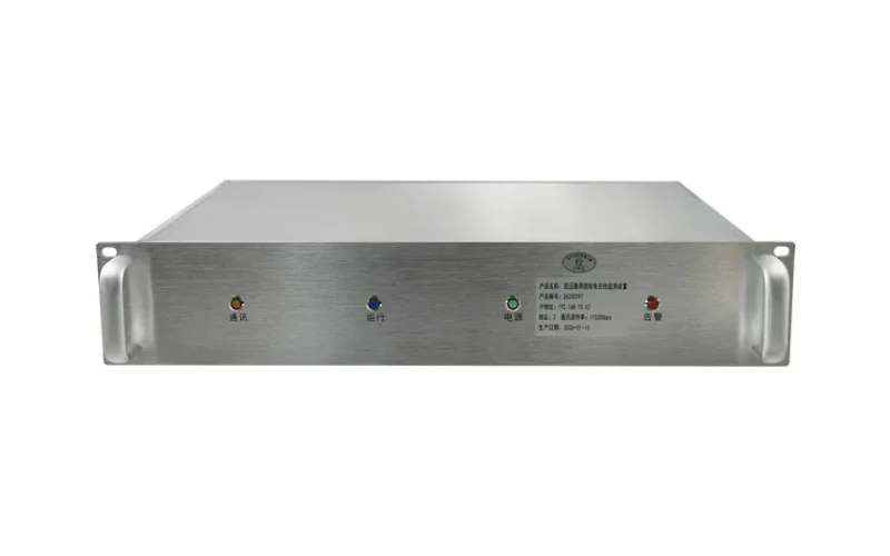
Überwachungssystem für Verteilungstransformatoren: Parameter, Kommunikation und Einsatz
Veröffentlichungsdatum:2. Oktober 2026, 17:12:31 Uhr
- What it is: a Transformatorüberwachungssystem is a set of sensors, local controllers, a communication gateway and a data platform that tracks the health of a distribution transformer in real time.
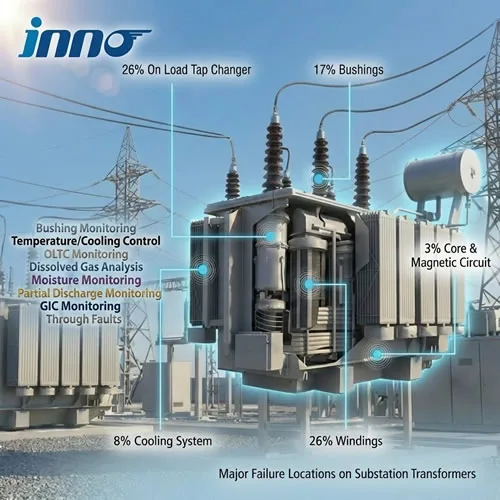
- Parameters to measure: winding temperature, top oil temperature, load current, oil level and pressure are the baseline. Dissolved gases, partial discharge, bushing condition and tap changer status are added for critical units.
- Communication: RS485/Modbus RTU for local devices, Modbus TCP, IEC 60870-5-104 or DNP3 to SCADA, and IEC 61850 in digital substations. Local alarm and trip must keep working if the network fails.
- Deployment: collect nameplate data, choose sensors by transformer type and criticality, route cables away from live parts, verify every channel against a reference, test alarm contacts, then calibrate once a year.
- Typical configurations: a temperature controller for dry-type units, a winding and oil temperature indicator for standard oil-immersed units, and fiber optic hot spot sensing plus online DGA for critical assets.
Inhaltsverzeichnis
- 1. Monitoring Parameters for Distribution Transformer Sensors and Transmitters
- 2. Dry-Type Transformer Temperature Controller and Fan Control
- 3. Oil-Immersed Winding Temperature Indicator and Oil Temperature Indicator
- 4. Fiber Optic Temperature Sensor and Demodulator for Hot Spot Monitoring
- 5. Online DGA Monitor for Critical Distribution Transformers
- 6. Partial Discharge, Bushing and OLTC Monitoring Devices
- 7. Communication Gateway, Modbus, IEC 61850 and SCADA Integration
- 8. Alarm, Trip and Relay Output Settings
- 9. Deployment and Commissioning Checklist for Monitoring Devices
- 10. Selection Matrix: Temperature Controller vs Fiber Optic System vs DGA Monitor
- 11. FAQ: Distribution Transformer Monitoring System Questions
1. Monitoring Parameters for Distribution Transformer Sensors and Transmitters
Baseline parameter table
| Parameter | Sensor / Source | Typical Sampling Interval | Priorität |
|---|---|---|---|
| Winding (hot spot) temperature | Fiber optic probe, Pt100 or winding temperature indicator | 1–10 s | Hoch |
| Maximale Öltemperatur | Oil temperature indicator or Pt100 | 1–60 s | Hoch |
| Load current and voltage | CT / PT or multifunction meter | 1 s | Hoch |
| Oil level and pressure | Level and pressure transmitters | 10–60 s | Mittel |
| Gelöste Gase | Online-DGA-Monitor | 1–24 h | Medium to high |
| Teilentladung | UHF, HFCT or acoustic sensor | Continuous | Medium to high |
| Bushing capacitance and tan δ | Bushing tap adapter | Continuous | Mittel |
| Cabinet temperature and humidity | Environmental sensor | 1–5 min | Niedrig |
Scope by transformer type
- Dry-type (cast resin or VPI): winding temperature per phase, fan status, enclosure temperature and humidity.
- Oil-immersed, standard: top oil temperature, winding temperature, oil level, load current.
- Oil-immersed, critical: add fiber optic hot spot sensing, online DGA and bushing monitoring.
- With on-load tap changer: add tap position, motor current and a gas or moisture sensor in the OLTC compartment.
2. Dry-Type Transformer Temperature Controller and Fan Control
What the controller must do
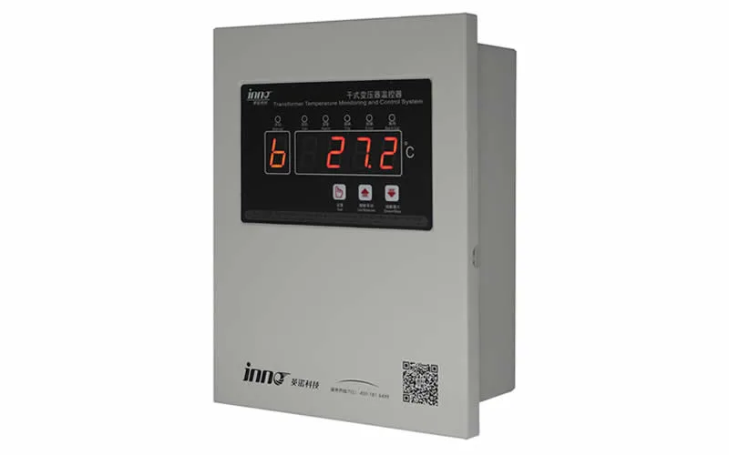
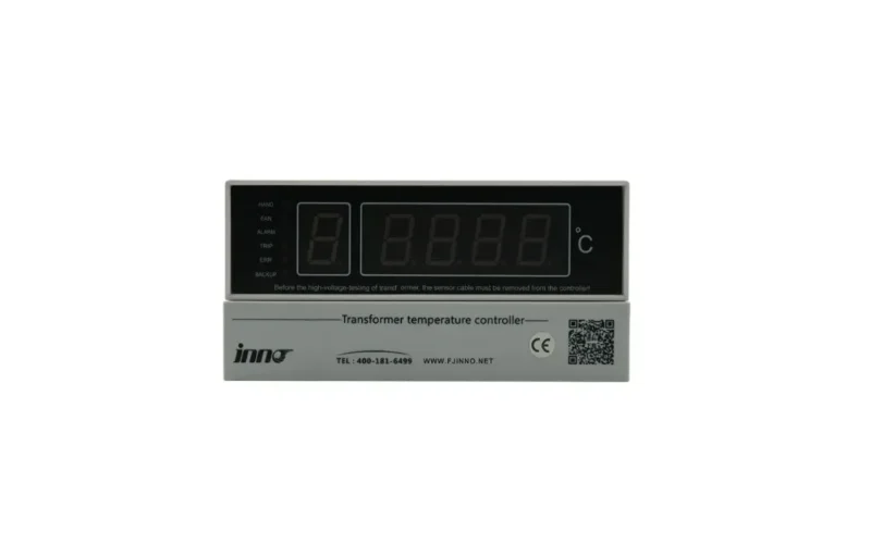
- Read three phase sensors: one Pt100 per phase winding, plus an optional core or enclosure channel. A dedicated device such as the IB-S201 Temperaturüberwachungs- und -regelgerät für Trockentransformatoren handles these inputs locally.
- Drive cooling fans: start and stop fans through a relay with hysteresis so they do not chatter around the setpoint.
- Provide alarm and trip relays: two independent dry contacts, wired to the protection circuit and not only to SCADA.
- Offer RS485 output: Modbus RTU registers for temperatures, relay states and sensor-fault flags.
- Detect sensor faults: open-circuit and short-circuit detection prevents a broken probe from reading as a normal temperature.
Insulation class and temperature reference
| Isolationsklasse | Maximale Wicklungstemperatur | Durchschnittlicher Wicklungsanstieg (IEC 60076-11) |
|---|---|---|
| Klasse B | 130 °C | 80 K |
| Klasse F | 155 °C | 100 K |
| Klasse H | 180 °C | 125 K |
Installation points
- Insert Pt100 probes into the winding air ducts of the middle section of each LV winding, where the hot spot usually sits.
- Keep sensor leads away from HV connections and use shielded cable grounded at the controller end only.
- Check that the controller supply voltage matches the available auxiliary supply (AC 220 V or DC 24–110 V).
3. Oil-Immersed Winding Temperature Indicator and Oil Temperature Indicator
How the two gauges differ
- Oil temperature indicator (OTI): a capillary or electronic probe in a pocket at the top-oil position that reads top oil temperature directly.
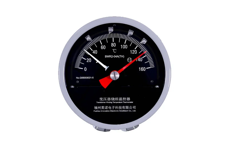
- Winding temperature indicator (WTI): a thermal-image device. A Anzeige der Wicklungstemperatur adds a heating-element offset, driven by a load current from a CT, to the top oil temperature to estimate hot spot temperature.
- Limit of the thermal image: the estimate depends on correct CT ratio, heater calibration and gradient data, so it can drift from the real hot spot under changing load.
Parameter comparison
| Artikel | Oil Temperature Indicator | Anzeige der Wicklungstemperatur |
|---|---|---|
| Measured value | Maximale Öltemperatur | Calculated winding hot spot |
| Typical scale | 0–120 °C | 0–150 °C |
| Contacts | 2–4 adjustable (fan, alarm, trip) | 2–4 adjustable (fan, alarm, trip) |
| Extra input | Keine | CT current (typically 0–5 A) |
| Fernausgang | Pt100 or 4–20 mA | Pt100 or 4–20 mA |
Setup points
- Fill the OTI pocket with transformer oil so heat transfers properly to the probe.
- Set the WTI heater current from the transformer test report so the gradient matches the nameplate.
- Add a 4–20 mA or Pt100 transmitter output when the readings must reach SCADA.
4. Fiber Optic Temperature Sensor and Demodulator for Hot Spot Monitoring
Why fiber optic probes measure the hot spot directly
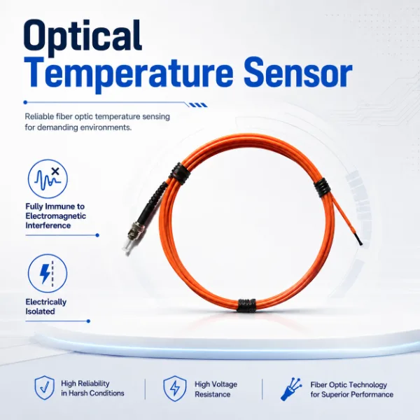
- Dielectric probe: the sensing tip has no metal, so it sits against HV windings without creating a discharge path.
- Störfestigkeit gegenüber elektromagnetischen Störungen: readings stay stable in strong magnetic and electric fields where electrical sensors pick up noise.
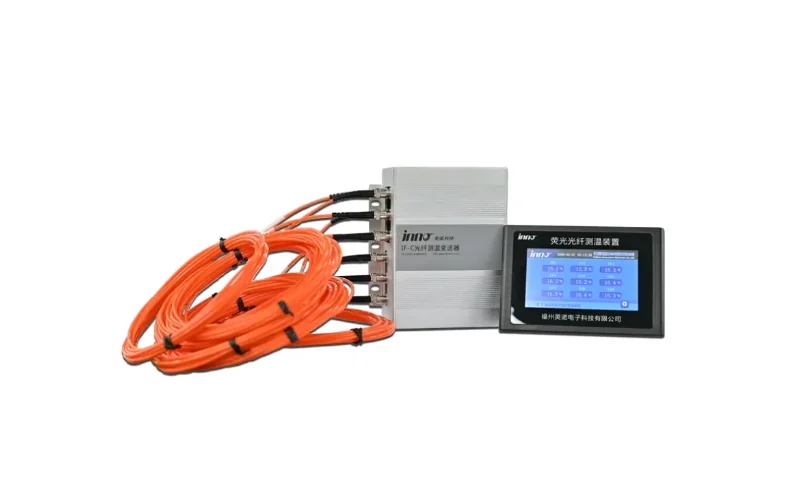
- Direct reading: there is no thermal-model estimate, which matters when overload decisions depend on a few degrees. The principle is explained in more detail in Glasfaser-Temperaturmessung in Transformatoren.
Typical system parameters
| Artikel | Typischer Wert |
|---|---|
| Messbereich | -40 °C bis 200 °C |
| Genauigkeit | ±1 °C |
| Reaktionszeit | ≤ 1 s |
| Channels per demodulator | 1, 3, 6 oder bis zu 64 |
| Ausgabe | RS485 Modbus, 4–20 mA, relay |
| Probe insulation withstand | Suitable for HV winding contact (confirm with datasheet) |
Method comparison
| Verfahren | Maßnahmen | EMI-Störfestigkeit | Optimale Passform |
|---|---|---|---|
| Pt100 on enclosure or pocket | Indirect temperature | Moderate | Dry-type air or basic oil monitoring |
| Thermal-image WTI | Calculated hot spot | High (mechanical) | Standard oil-immersed units |
| Fiber optic probe | Direct hot spot | Hervorragend | Critical or high-load units |
Auswahlkriterien
- Channel count: a 3-channel module covers one three-phase dry-type unit, while a multi-channel demodulator suits several transformers in one substation.
- Probe type: choose armored probes for oil-immersed windings and polyimide-coated probes for resin or dry-type windings.
- Extension cable: measure the run from the tank wall or winding exit to the demodulator before ordering.
5. Online DGA Monitor for Critical Distribution Transformers
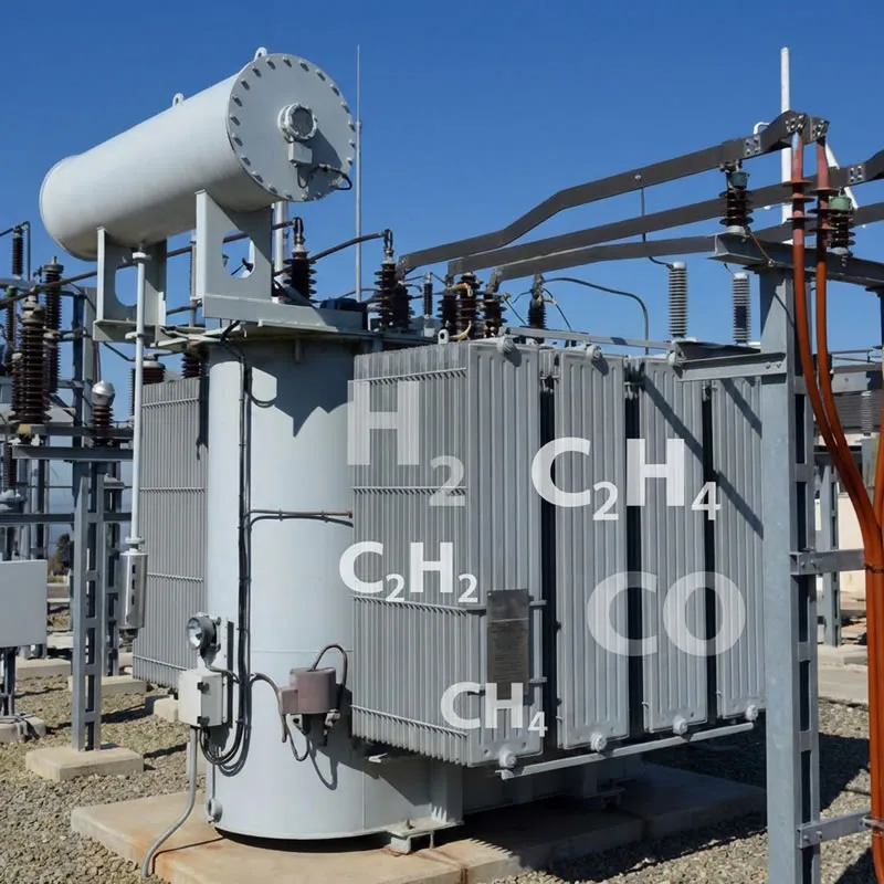
When online DGA is justified
- The transformer feeds hospitals, data centers, rail traction or process lines where an outage is costly.
- Periodic oil samples show a rising gas trend, and waiting for the next sampling date is not acceptable.
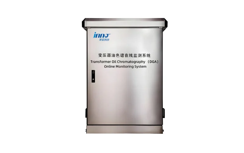
- The site is remote or unmanned, so manual sampling is expensive. The trade-offs are covered in Online-DGA-Überwachung von Transformatoren.
Key gases and what they indicate
| Gas | Typical Fault Indication |
|---|---|
| Wasserstoff (H₂) | Partial discharge, general low-energy fault |
| Methane (CH₄), Ethane (C₂H₆) | Low to medium temperature overheating |
| Ethylen (C₂H₄) | High temperature overheating |
| Acetylen (C₂H₂) | Arcing or very high temperature |
| CO, CO₂ | Cellulose (paper) insulation overheating |
Auswahlkriterien
- Gas coverage: single-gas (H₂ or composite) monitors suit screening, while multi-gas units support Duval triangle and IEC 60599 interpretation.
- Interpretation basis: use IEEE C57.104 or IEC 60599 limits and watch the rate of gas increase, not only absolute values.
- Mounting: install on the drain or sampling valve with an isolation valve so the monitor can be serviced without draining the tank.
6. Partial Discharge, Bushing and OLTC Monitoring Devices
Partial discharge sensors
- UHF sensors on the drain valve detect internal discharge with good noise rejection.
- HFCT sensors on bushing taps or the ground strap suit retrofit work.
- Acoustic sensors on the tank help localize the source. A complete overview of methods is in Überwachung von Teilentladungen in Transformatoren.
Überwachung von Buchsen
- Measured values: capacitance change and dissipation factor (tan δ), compared between phases.
- Why it matters: bushing insulation faults can lead to tank rupture or fire, so trend-based bushing monitoring is worth adding on high-value units.
OLTC-Überwachung
- Measured values: tap position, drive motor current or torque, operation counter and temperature difference between the OLTC compartment and the main tank.
- Typical fault clues: rising motor current, slower operation time and contact wear signs, which OLTC transformer monitoring can trend over time.
7. Communication Gateway, Modbus, IEC 61850 and SCADA Integration
Protocol table
| Interface / Protocol | Typische Anwendung | Mittel | Anmerkungen |
|---|---|---|---|
| RS485 / Modbus RTU | Controllers and sensors to gateway | Shielded twisted pair | Up to about 1200 m at 9600 bps |
| Modbus TCP | Gateway to PLC or SCADA | Ethernet | Simple and widely supported |
| IEC 60870-5-104 / DNP3 | Utility telecontrol | Ethernet / IP | Common in grid operations |
| IEC 61850 | Digital substations | Ethernet | Needs ICD/SCD file mapping |
| 4–20 mA / dry contact | Legacy RTU and alarm panels | Copper | Suitable for retrofit projects |
| 4G / 5G / fiber backhaul | Remote unmanned sites | Wireless / fiber | Use VPN and firewall |
Data architecture points
- Protect the local layer: alarm and trip relays must act independently of the network.
- Standardize tags: use one naming and register map across all transformers, as described in transformer monitoring dashboard and SCADA integration.
- Synchronize time: use NTP or IRIG-B so events from different devices can be correlated.
- Secure remote access: role-based accounts, encrypted links and disabled unused ports.
8. Alarm, Trip and Relay Output Settings
Four-stage alarm scheme
| Bühne | Relay Action | Setting Basis |
|---|---|---|
| Lüfterstart | Start cooling fans | Below alarm, per manufacturer |
| Pre-alarm | Notify operator, review load | Insulation class and loading guide |
| Alarm | Dispatch inspection, reduce load | Nameplate temperature rise |
| Reise | Disconnect the transformer | Maximum permissible temperature |
Example starting points
| Transformatortyp | Lüfter starten | Alarm | Reise |
|---|---|---|---|
| Dry-type Class F winding | 100–110 °C | 130 °C | 150 °C |
| Dry-type Class H winding | 120–130 °C | 155 °C | 170–180 °C |
| Oil-immersed top oil | 65–75 °C | 80–85 °C | 95–105 °C |
Regeln festlegen
- Treat the values above as starting points only and confirm every setpoint against the nameplate and manufacturer manual.
- Base overload permissions on transformer temperature rise limits and IEC 60076-7 or IEEE C57.91 loading guides.
- Add a 2–5 °C hysteresis to the fan relay to avoid rapid cycling.
- Record every setpoint change with date, reason and approver.
9. Deployment and Commissioning Checklist for Monitoring Devices
Before installation
- Collect rating, cooling type, insulation class, temperature rise and test report data.
- Decide whether the unit is new, where sensors can be embedded, or in service, where only retrofit options exist.
- Define the sensor list, controller model, gateway and power supply.
- Confirm the SCADA protocol and register map with the control team.
- Agree on the outage window and safety clearances.
During installation
- Route fiber and signal cables away from HV live parts and respect the minimum bend radius.
- Ground cable shields at one end only.
- Seal cable glands against moisture, especially on outdoor pad-mount units.
- Label every channel, cable and terminal to match the drawings.
Commissioning tests
| Test | Verfahren | Bestehenskriterium |
|---|---|---|
| Temperature channel check | Compare with reference thermometer | Im Rahmen der Gerätegenauigkeit |
| Relay output test | Simulate setpoints, check contacts | Correct fan, alarm and trip action |
| Sensor fault test | Disconnect probe | Fault flag raised |
| Communication test | Read all registers from SCADA | Die Werte entsprechen der lokalen Anzeige |
Nach der Inbetriebnahme
- Write a response procedure for each alarm level and train the operators.
- Store baseline readings at known loads for later comparison.
- Schedule an annual check of sensors, wiring, contacts and communication.
10. Selection Matrix: Temperature Controller vs Fiber Optic System vs DGA Monitor
| Scenario | Suggested Configuration | Kommunikation |
|---|---|---|
| Indoor dry-type, commercial building | Temperature controller with fan output | RS485 / Modbus RTU |
| Standard oil-immersed distribution unit | WTI and OTI with optional transmitter | Dry contact or 4–20 mA |
| High-load oil-immersed unit | Fiber optic hot spot system | Modbus TCP / IEC 104 |
| Critical asset feeding sensitive loads | Fiber optic, online DGA and bushing monitor | IEC 61850 / SCADA |
| Voltage-regulating unit with OLTC | Temperature plus OLTC and DGA monitor | Modbus TCP / DNP3 |
11. FAQ: Distribution Transformer Monitoring System Questions
What does a distribution transformer monitoring system include?
It includes temperature sensors or indicators, a local controller with alarm and fan relays, optional DGA, partial discharge and bushing sensors, a communication gateway and a SCADA or cloud platform.
Which parameters should I monitor first?
Start with winding temperature, top oil temperature and load current. Add oil level, dissolved gases, partial discharge and bushing data when the transformer is critical or high-value.
How does monitoring differ between dry-type and oil-immersed transformers?
Dry-type units focus on winding temperature and fan control because they rely on air cooling. Oil-immersed units add oil temperature, level, pressure and, where justified, DGA.
When should I use a fiber optic temperature sensor instead of a Pt100 or WTI?
Use fiber optic sensing when you need direct hot spot readings, high accuracy and immunity to electromagnetic interference, usually on critical or heavily loaded units. Pt100 and WTI are usually adequate for lightly loaded general-purpose transformers.
Welches Kommunikationsprotokoll soll ich wählen?
Modbus RTU or TCP suits most industrial and commercial projects. Utilities usually use IEC 60870-5-104 or DNP3, and digital substations use IEC 61850. Choose the protocol your control system already supports.
Can I add monitoring to a transformer already in service?
Yes. Oil temperature probes, WTI, current-based load monitoring, online DGA and external PD or bushing sensors can be retrofitted. Embedded winding probes are normally installed during manufacture or major overhaul.
Does every distribution transformer need online DGA?
No. Online DGA is typically kept for critical units. For many distribution transformers, temperature monitoring plus periodic sampling is sufficient, as compared in online DGA vs oil sampling.
How often should the monitoring system be calibrated?
Follow the manufacturer's interval. A common practice is an annual functional check of sensors, alarm contacts and communication, with recalibration if drift is found.
How do I get a configuration for my project?
Prepare the transformer type, rating, cooling method, insulation class and communication requirement, then Leiten Sie diese an das Entwicklerteam weiter for a matched monitoring scheme.