Giám sát nhiệt độ máy biến áp kiểu khô: Vị trí lắp đặt cảm biến, cài đặt cảnh báo và lựa chọn kênh
发布时间:Ngày 6 tháng 10 năm 2026, 15:02:06
- Sensor locations: place one Pt100 probe in the air duct of each LV winding (phases A, B and C), in the upper-middle section where the hot spot usually forms. Add an optional core channel and an enclosure or ambient channel.
- Alarm settings: base them on the insulation class. Typical starting points for Class F are fan start at 100–110 °C, alarm at 130 °C and trip at 150 °C. For Class H they are 120–130 °C, 155 °C and 170–180 °C. Always confirm against the nameplate.
- Channel selection: 3 channels cover the three phase windings, 4 channels add the core, and 6 channels give redundant probes for critical units. Use a multi-channel unit when one panel serves several transformers.
- Sensor type: Pt100 suits standard dry-type units, while fiber optic probes suit cast resin or high-load transformers that need direct hot spot readings.
- Outputs: a monitor should provide fan, alarm and trip relays plus RS485 Modbus, and it should detect sensor faults.
Mục lục
- 1. Pt100 Sensor Locations in LV Winding Air Ducts
- 2. Core Temperature Probe and Enclosure Ambient Sensor Placement
- 3. Polyimide Fiber Optic Probe for Cast Resin Winding Hot Spots
- 4. Temperature Controller Functions: Fan, Alarm, Trip and Fault Relays
- 5. Alarm Settings by Insulation Class: Class B, F and H Set Points
- 6. Channel Selection: 3-Channel, 4-Channel and 6-Channel Monitors
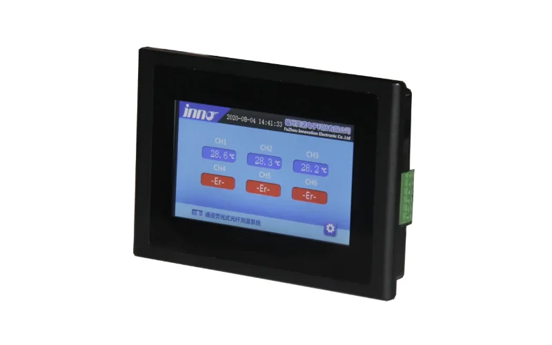
- 7. Fiber Optic Temperature Module and Demodulator Channel Count
- 8. RS485 Modbus Output, Gateway and Remote Display
- 9. Pt100 Wiring, Shielding and Cable Routing Rules
- 10. Commissioning and Calibration Tests for Temperature Monitors
- 11. FAQ: Dry-Type Transformer Temperature Monitoring Questions
1. Pt100 Sensor Locations in LV Winding Air Ducts
Where the hot spot forms
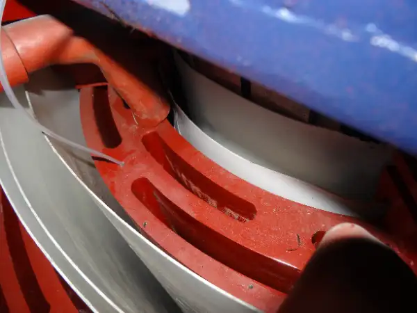
In a dry-type transformer, heat is carried away by air, so the hottest point sits inside the winding rather than on its surface. For most cast resin and VPI designs, the hot spot is found in the upper-middle part of the LV winding, because cooling air warms as it rises through the duct. The center phase (B) is often the hottest because its neighbors restrict airflow on both sides.
Recommended probe positions
- One probe per phase: insert a Pt100 into the air duct between the LV winding layers of phases A, B and C.
- Height: follow the manufacturer's marked sensor pocket or duct position. If none is marked, use the upper-middle section of the winding height.
- Contact: the probe tip should touch the duct surface and not hang in free air, otherwise readings lag behind the real temperature.
- Fixing: secure the probe lead with a non-metallic tie so vibration does not move it.
Sensor location reference
| Measuring Point | Typical Position | Mục đích | Priority |
|---|---|---|---|
| Phase A winding | LV air duct, upper-middle | Alarm and trip | High |
| Phase B winding | LV air duct, upper-middle | Alarm and trip | High |
| Phase C winding | LV air duct, upper-middle | Alarm and trip | High |
| Core | Upper yoke or core leg surface | Core overheating detection | Medium |
| Enclosure / ambient | Air inlet or room near the unit | Cooling condition reference | Thấp |
2. Core Temperature Probe and Enclosure Ambient Sensor Placement
Core probe
- Why monitor the core: a core temperature that rises out of proportion to load can indicate lamination short circuits, a multiple core grounding fault or poor ventilation.
- Placement: attach a surface-type Pt100 to the top yoke or a core leg with heat-resistant tape or a clamp, away from direct winding contact.
Ambient or enclosure sensor
- Purpose: it separates a hot room from a hot transformer. If winding temperature and room temperature rise together, the problem is ventilation and not the transformer.
- Placement: mount it near the cooling air inlet, shielded from direct radiation from the windings.
Use of each channel in the logic
| Channel | Used for Fan Control | Used for Alarm | Used for Trip |
|---|---|---|---|
| Winding A / B / C | Yes (highest value) | Đúng vậy | Đúng vậy |
| Core | Tùy chọn | Yes (separate set point) | Usually no |
| Ambient | No | Optional (room over-temperature) | No |
3. Polyimide Fiber Optic Probe for Cast Resin Winding Hot Spots
When to choose fiber optic instead of Pt100
- Direct hot spot reading: a fiber optic probe can be embedded between winding layers, so it reads the winding itself and not the duct air.
- High-voltage safety: the probe is dielectric, so it creates no discharge path when placed against HV windings.
- EMI immunity: readings stay stable in strong fields, where long Pt100 leads can pick up noise. The principle is explained in fiber optic temperature measurement in transformers.
- Probe construction: a polyimide fiber optic temperature sensor tolerates the curing temperature of cast resin and suits embedding during manufacture.
Pt100 and fiber optic comparison
| Item | Pt100 Probe | Fiber Optic Probe |
|---|---|---|
| Typical installation | Air duct, retrofit possible | Embedded in winding at manufacture |
| What it reads | Duct or surface temperature | Winding hot spot |
| Typical accuracy | ±0.5 °C to ±1 °C (system) | ±1 °C |
| Khả năng chống nhiễu điện từ | Moderate (shielding needed) | Excellent |
| Cost | Thấp | Higher |
| Best fit | Standard commercial units | Critical, high-load or high-voltage units |
4. Temperature Controller Functions: Fan, Alarm, Trip and Fault Relays
Required functions
- Fan control relay: starts and stops the cooling fans from the highest winding temperature, with hysteresis to prevent chatter.
- Alarm relay: a dry contact for the alarm panel or SCADA input.
- Trip relay: a separate contact wired to the upstream breaker's protection circuit.
- Sensor fault output: detects open or shorted probes, so a broken wire does not read as a normal temperature.
- Display: shows each phase value, with a maximum-value hold and a channel scan mode.
Controller options
Panel-mount controllers
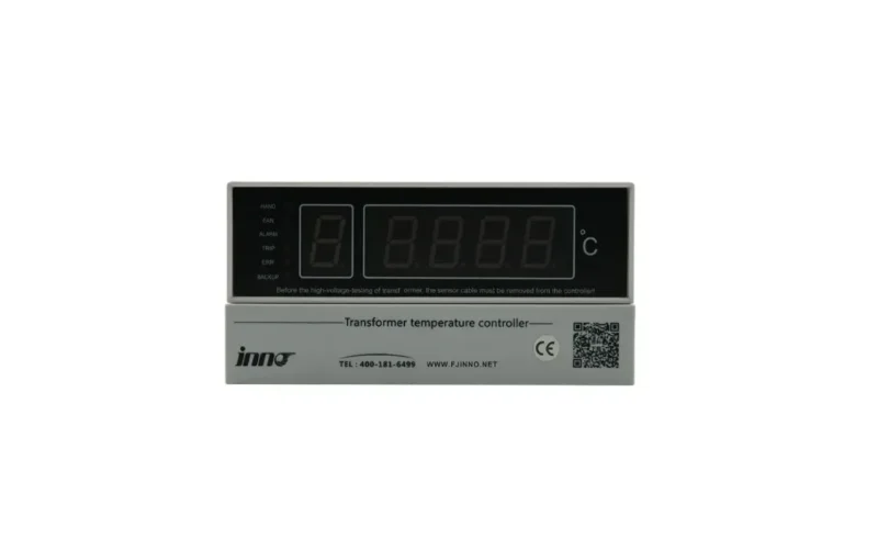
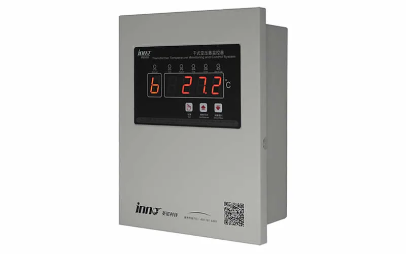
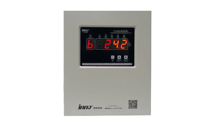
A unit such as the IB-S201 dry-type transformer temperature monitor and controller combines three-phase inputs, fan control, alarm and trip relays, and an RS485 port in one device, which suits standard indoor dry-type units.
Integrated intelligent monitors
When the project also needs load, harmonics or enclosure data, an intelligent monitoring device or a complete online health monitoring system for dry-type transformers can combine these in a single platform.
Controller parameter reference
| Item | Typical Value |
|---|---|
| Input type | Pt100, 3-wire |
| Measuring range | 0–200 °C (or wider) |
| Display resolution | 1 °C or 0.1 °C |
| Relay outputs | Fan, alarm, trip, fault |
| Relay contact rating | AC 250 V / 5 A (check datasheet) |
| Communication | RS485 Modbus RTU |
| Auxiliary supply | AC 220 V or DC 24–110 V |
5. Alarm Settings by Insulation Class: Class B, F and H Set Points
Insulation class reference
| Insulation Class | Max Winding Temperature | Average Winding Rise (IEC 60076-11) |
|---|---|---|
| Class B | 130 °C | 80 K |
| Class F | 155 °C | 100 K |
| Class H | 180 °C | 125 K |
Typical starting set points
| Insulation Class | Fan Start | Fan Stop | Alarm | Trip |
|---|---|---|---|---|
| Class B | 80–90 °C | 70–80 °C | 110–120 °C | 130 °C |
| Class F | 100–110 °C | 90–100 °C | 130 °C | 150 °C |
| Class H | 120–130 °C | 110–120 °C | 155 °C | 170–180 °C |
Setting rules
- Nameplate first: these values are starting points. Use the manufacturer's nameplate and manual as the final authority.
- Hysteresis: set the fan stop point 10 °C or so below fan start, so fans do not cycle rapidly.
- Alarm margin: keep the alarm 15–25 °C below the trip point, so operators have time to reduce load.
- Trip below class limit: keep trip at or below the insulation class maximum. Loading and ageing limits are described in transformer temperature rise limits and ratings.
- Core and ambient alarms: set the core alarm from the factory test report, and set an ambient alarm near the room design limit (for example 40 °C).
- Change log: record every set point change with date, reason and approver.
6. Channel Selection: 3-Channel, 4-Channel and 6-Channel Monitors
How to pick the channel count
- 3 channels: the minimum for a three-phase unit, with one probe on each LV winding.
- 4 channels: three windings plus the core, which suits most commercial and industrial installations.
- 6 channels: three windings with redundant probes, or windings plus core, ambient and fan-side points, which suits critical units.
- 8 or more channels: one panel monitoring several transformers in the same room, or both HV and LV windings.
Channel selection matrix
| Ứng dụng | Recommended Channels | Probe Arrangement | Output |
|---|---|---|---|
| Small commercial building unit | 3 | A, B, C windings | Relays, RS485 |
| Industrial plant unit | 4 | A, B, C windings and core | Relays, RS485 |
| Critical unit (hospital, data center) | 6 | A, B, C windings with spare probes | Relays, RS485, SCADA |
| Two or three units in one room | 9–12 | 3 windings per transformer | RS485, SCADA |
| Large substation or tunnel | 16–64 (fiber optic) | Multiple transformers on one demodulator | Modbus TCP, IEC 104 |
Spare channel planning
- Leave at least one spare channel per transformer, because probes are the most common failure point in the system.
- Plan the sensor naming (T1-A, T1-B, T1-C) before wiring, so channel labels match SCADA tags.
7. Fiber Optic Temperature Module and Demodulator Channel Count
Choosing a module
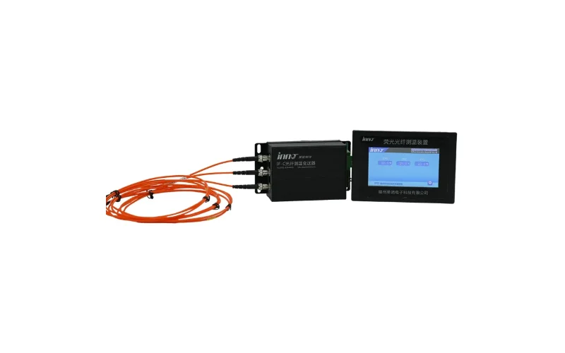
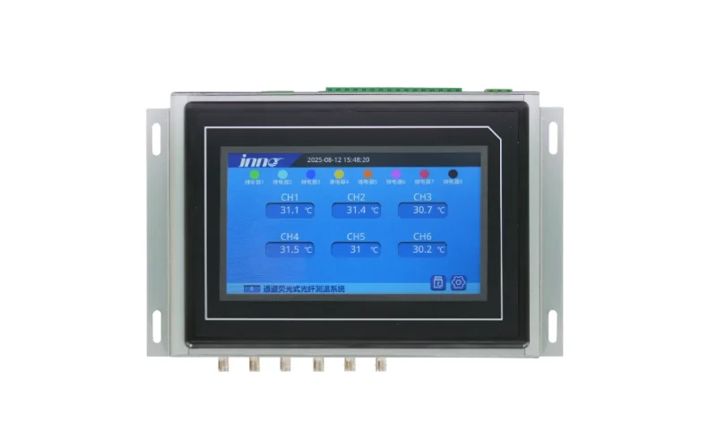
- Three-phase unit: an IF-G3 3-channel fiber optic temperature sensing module covers the three windings of one transformer.
- Redundant or multi-point units: a 6-channel fluorescent demodulator supports two probes per phase, or winding plus core points.
- Several transformers: a multi-channel system, up to 64 channels, keeps one cabinet for a whole transformer room.
Fiber optic system reference
| Item | Typical Value |
|---|---|
| Measuring range | -40 °C to 200 °C |
| Độ chính xác | ±1 °C |
| Thời gian phản hồi | ≤ 1 s |
| Channels | 1, 3, 6 or up to 64 |
| Outputs | RS485 Modbus RTU, 4–20 mA, relay |
| Probe lead length | Custom, extendable with extension cable |
Selection points
- Measure the cable run from the winding exit to the demodulator before ordering, and add an extension cable if needed.
- Keep the minimum bend radius of the fiber, because tight bends cause signal loss.
- Embedded probes cannot be replaced once the resin has cured, so order spare channels and probes at the design stage.
8. RS485 Modbus Output, Gateway and Remote Display
Typical data points over Modbus RTU
| Data Point | Type | Use |
|---|---|---|
| Winding temperature A / B / C | Analog value | Trend and alarm |
| Core and ambient temperature | Analog value | Trend and diagnosis |
| Fan, alarm, trip state | Status bit | Event log |
| Sensor fault flags | Status bit | Data quality |
| Set points | Read / write value | Remote configuration |
Communication rules
- Cable: shielded twisted pair, with a total length up to about 1200 m at 9600 bps.
- Addressing: give each controller a unique Modbus address and the same baud rate and parity.
- Termination: add a 120 Ω terminating resistor at the far end of the bus.
- Independence: fan, alarm and trip relays must keep working if RS485 or the gateway fails.
- Remote display: use a separate display or HMI when operators need to read temperatures outside the transformer room.
9. Pt100 Wiring, Shielding and Cable Routing Rules
Wiring rules
- Three-wire connection: cancels the lead resistance, which would otherwise add error on long runs.
- Shielded cable: ground the shield at the controller end only, to avoid ground loops.
- Separation: keep sensor leads away from power cables and HV connections. Cross them at right angles when unavoidable.
- Heat-resistant leads: use PTFE or silicone-insulated cable inside the winding area.
- Strain relief: fix the cable near the probe so pulling on the cable does not move the sensor.
Common wiring faults
| Symptom | Likely Cause | Check |
|---|---|---|
| Reading jumps or is noisy | Shield not grounded or cable near power lines | Shield ground and routing |
| Reading is too high by a fixed value | Two-wire connection or lead resistance | Wiring mode and terminals |
| Reading shows maximum or overrange | Open probe or loose terminal | Probe continuity |
| Reading shows minimum or zero | Shorted probe or wire | Insulation and resistance |
| Reading lags behind load | Probe not in contact with duct surface | Probe position |
10. Commissioning and Calibration Tests for Temperature Monitors
Before energizing
- Confirm that each probe is in the correct phase, and match the channel label to the winding.
- Measure Pt100 resistance at room temperature. It should be close to 109–110 Ω at 25 °C.
- Check the auxiliary supply voltage against the controller rating.
- Enter set points from the nameplate and the insulation class.
Functional test table
| Test | Method | Pass Criterion |
|---|---|---|
| Channel accuracy | Use a Pt100 simulator or a reference thermometer | Within device accuracy |
| Fan relay | Simulate fan start and stop temperatures | Fans start and stop at set points |
| Alarm relay | Simulate the alarm temperature | Alarm contact closes, panel shows alarm |
| Trip relay | Simulate the trip temperature, with breaker in test position | Trip contact operates the breaker circuit |
| Sensor fault | Disconnect and short a probe | Fault flag and display warning |
| Communication | Read registers from SCADA | Values match local display |
After commissioning
- Record the winding temperature at 50%, 75% and 100% load as baseline values.
- Re-check the sensors and relay contacts once a year, and recalibrate if drift is found.
- Review the maximum temperature log after any overload or ventilation failure.
- For wider guidance on dry-type installations, see dry-type transformer temperature monitoring applications.
11. FAQ: Dry-Type Transformer Temperature Monitoring Questions
Where should temperature sensors be placed on a dry-type transformer?
Place one Pt100 probe in the air duct of each LV winding, in the upper-middle section where the hot spot usually forms. Add a core probe on the yoke or leg and an ambient sensor near the cooling air inlet if needed.
How many temperature channels do I need?
Three channels are the minimum for a three-phase unit. Use four channels to add the core, and six channels for redundant probes on critical transformers. Use a multi-channel unit when one panel serves several transformers.
What alarm and trip temperatures should I use?
They depend on the insulation class. Class F units commonly use an alarm near 130 °C and a trip near 150 °C, while Class H units use about 155 °C and 170–180 °C. Confirm all values against the nameplate and the manufacturer's manual.
Why does the center phase often read higher?
The center phase is surrounded by the other two windings, which restricts cooling airflow and adds heat from both sides. For this reason, controllers usually base fan control on the highest of the three phase readings.
Is a Pt100 or a fiber optic sensor better for dry-type transformers?
Pt100 probes are low in cost and suit standard units, with the option to retrofit into air ducts. Fiber optic probes are better for critical, high-voltage or heavily loaded units, because they read the winding hot spot directly and resist electromagnetic interference.
Can I add temperature monitoring to a transformer already in service?
Yes. Pt100 probes can usually be inserted into the winding air ducts and core surface during a short outage. Fiber optic probes embedded in the winding are normally installed during manufacture.
Why do the fans keep switching on and off?
Fan start and stop points are probably too close together. Set the stop temperature about 10 °C below the start temperature, and use the highest phase reading for control.
Should the controller trip relay depend on SCADA?
No. Fan, alarm and trip relays must operate inside the controller, independent of RS485, the gateway or the network. SCADA should receive the data for monitoring and trend analysis only.
How do I get a recommended channel configuration for my transformers?
Prepare the transformer rating, insulation class, number of units, voltage level and your communication requirement, then send them to the engineering team for a matched sensor and controller scheme.